Author Topic: thought experiment - self-controlled voltage reference  (Read 24979 times)

0 Members and 4 Guests are viewing this topic.

alm

  • Guest
Re: thought experiment - self-controlled voltage reference
« Reply #50 on: August 04, 2013, 12:02:18 pm »
LSTx is a smooth function of time that is monotonous and predictable: if you give me the first few points, then I can calculate LTS1, and predict the rest of LSTx. This looks very different from the graph I referred to in the LTZ1000 datasheet. As far as I see, the LT1236 datasheet does not show drift as a function of time, only the magnitude after 1000 h.

The simulation assumes that the ADC will perfectly measure the (noisy) reference voltage. Not sure how much impact it has on the results, but it will make measuring the average of two references kind of pointless: vin1_ref2_ref3 = (in1_ref2 + in1_ref3) / 2 (within one LSB).
 

Offline branadicTopic starter

  • Super Contributor
  • ***
  • Posts: 2452
  • Country: de
  • Sounds like noise
Re: thought experiment - self-controlled voltage reference
« Reply #51 on: August 04, 2013, 12:19:36 pm »
Okay, step-by-step:

- LTS is given with typ. 20ppm @1000h
- I generate a random value for each reference (LTS1, LTS2, LTS3) at the point t=1000h
- I now generate a function with log characteristic for each reference (LTSx, LTSy, LTSz)

See page 3 of the datasheet for long-term stability:

Note 6: Long-term stability typically has a logarithmic characteristic and therefore, changes after 1000 hours tend to be much smaller than before that time. Total drift in the second thousand hours is normally less than one third that of the first thousand hours, with a continuing trend toward reduced drift with time. Significant improvement in long-term drift can be realized by preconditioning the IC with a 100-200 hour, 125°C burn in.
Long term stability will also be affected by differential stresses between the IC and the board material created during board assembly. Temperature cycling and baking of completed boards is often used to reduce these stresses in critical applications.

I don't consider Output Voltage Temperature Coefficient into calculation, because I assume that the complete circuit is ovenized.

The simulation considers the 2:1 divider (LTC1043 * LTC1050) at the adc input into account. The adc is feet by on of the references, so the resolution of the adc is the actual reference voltage divided by 2^24.
Furthermore the acquired value by the adc is rounded to full integer, so what you get is a set of integer values over time for the different setups. So it's wrong when you say

Quote
The simulation assumes that the ADC will perfectly measure the (noisy) reference voltage

Clear up to here?
« Last Edit: August 04, 2013, 12:26:32 pm by branadic »
Computers exist to solve problems that we wouldn't have without them. AI exists to answer questions, we wouldn't ask without it.
 

alm

  • Guest
Re: thought experiment - self-controlled voltage reference
« Reply #52 on: August 04, 2013, 01:40:42 pm »
Drift will decrease over time, that's what you also see in the LT1000 datasheet. But it won't be the perfectly smooth process that (apart from the magnitude) is identical for all references. In the ref5025 datasheet is another set of curves showing real-world long-term stability data:


If an ADC is perfect, then it will measure the input to one LSB. But ADCs have noise. Even if you short the input to ground (a very low noise, low impedance input) and take a bunch of readings, you get a distribution of output values, for example:


Good case


Bad case.

Both figures come from Analog Devices: ADC Input Noise: The Good, The Bad, and The Ugly. Is No Noise Good Noise?.

If you take one reading of say Vref/2, then the output might be anywhere within 2^23+/- 4 counts for this ADC with a good board layout.

Plus you will get non-linearity errors:

(From the LTC2400 datasheet)

Although you can calibrate this out, as was done in LT AN86 through a fairly elaborate procedure. No calibration will get rid of noise, however, although averaging helps.
« Last Edit: August 04, 2013, 01:42:36 pm by alm »
 

Offline robrenz

  • Super Contributor
  • ***
  • Posts: 3035
  • Country: us
  • Real Machinist, Wannabe EE
Re: thought experiment - self-controlled voltage reference
« Reply #53 on: August 04, 2013, 02:51:31 pm »
I have personal experience in the three plate method of obtaining flat surfaces having hand scraped three 18"square surface plates to within 15µ" flatness over 35 years ago. Just like this electronic discussion, there are many things that limit the achievable results when you try to get below certain levels. The modulus of elasticity of the material (rigidity) affects how much the plates conform to each other elastically and are deformed by gravity. Vertical thermal gradient of the environment directly affects the curvature of the surface because most materials have some thermal coefficient of expansion (equivalent to a bimetallic strip curvature with delta temp). That means even in zero gravity just turning a plate over will change its curvature from vertical thermal gradient affects. Unless you take extreme measures all rooms have a vertical thermal gradient that varies with seasons.  My point is, a method that on the surface appears foolproof and exact usually falls apart if you start to measure at low enough resolution and consider all the minute physics details.

Offline branadicTopic starter

  • Super Contributor
  • ***
  • Posts: 2452
  • Country: de
  • Sounds like noise
Re: thought experiment - self-controlled voltage reference
« Reply #54 on: August 04, 2013, 03:14:32 pm »
I think you didn't got my simulation model up to now.

You are right if you say drift decreases and long-term stability improves over time. This is what I model for each of the three references, but with a random value for each of the three references after 1000h. I'm optimistic for the moment and say the value for long-term stability after 1000h is max. 20ppm, the typical given value of the datasheet for the LT1236LS8. The behaviour is a log expression and you can see that on page 8 of the LT1236LS8 datasheet.
So what you see is a random start value for each reference between 4.9975V and 5.0025V plus a drift with random value after 1000h for each reference and log behaviour plus a random noise (I assume the integration time is 1s so I take the noise voltage of max. 625nVpp).
This together gives a different walk for each reference.

Got it up to here?
Computers exist to solve problems that we wouldn't have without them. AI exists to answer questions, we wouldn't ask without it.
 

Offline branadicTopic starter

  • Super Contributor
  • ***
  • Posts: 2452
  • Country: de
  • Sounds like noise
Re: thought experiment - self-controlled voltage reference
« Reply #55 on: August 04, 2013, 03:26:39 pm »
The three plate methode is a limited example compared to the example we discuss in here.
We don't won't to talk about the point where you have reached the "perfect surface" and than use the plates in real world apllication, but we talk about the way of manufacturing such a plate.
It is known that you have to exchange the plates against each other while manufacturing them. You will get down to a certain deviation compared to an ideal flat surface, depending on several conditions. From this point on the deviation will again increase. You would stop at this point and sale the plates or bring them into application.
Your plates are and this is different, correlated against each other, so this is the point where the examples reaches its limits.
Computers exist to solve problems that we wouldn't have without them. AI exists to answer questions, we wouldn't ask without it.
 

Offline branadicTopic starter

  • Super Contributor
  • ***
  • Posts: 2452
  • Country: de
  • Sounds like noise
Re: thought experiment - self-controlled voltage reference
« Reply #56 on: August 04, 2013, 03:53:42 pm »
Attached is a set of data that contains time and the random inital value, random noise and random drift for three references.
Computers exist to solve problems that we wouldn't have without them. AI exists to answer questions, we wouldn't ask without it.
 

alm

  • Guest
Re: thought experiment - self-controlled voltage reference
« Reply #57 on: August 04, 2013, 05:25:12 pm »
Over what time was that noise figure measured? In long term drift data, you see fluctuations in output voltage on the time scale of hours. You don't capture this in either your noise or long term drift data.

Let's compare your results to the datasheet graph:


Not a good fit to the supposed log expression.
« Last Edit: August 04, 2013, 05:41:39 pm by alm »
 

Offline branadicTopic starter

  • Super Contributor
  • ***
  • Posts: 2452
  • Country: de
  • Sounds like noise
Re: thought experiment - self-controlled voltage reference
« Reply #58 on: August 04, 2013, 05:59:32 pm »
I have the feeling I repeat myself over and over and you don't understand. You will agree that you can't model absolut real world data, right?
Don't deal with wrong notations, noise figure is something completely different! As visible and written I assumed to acquire one value per hour with an integration time of 1s, so the noise is within 625nVpp for each value.
The fluctuations you mentioned in the measured data are common mode fluctuations, we are not able to find out what happened there.

Quote
Not a good fit to the supposed log expression.

Okay, but then the additional text in the datasheet is wrong, wouldn't you agree? And notice that the shown graph is up to 2000h, while I do my calculations only up to 1000h at the moment, because specification for long-term stability is given at that time stamp.
Computers exist to solve problems that we wouldn't have without them. AI exists to answer questions, we wouldn't ask without it.
 

alm

  • Guest
Re: thought experiment - self-controlled voltage reference
« Reply #59 on: August 04, 2013, 06:37:15 pm »
If there is real world data, then that is what you're trying to match in a simulation. Not individual fluctuations, but at least the power spectra should look similar. You first try to match real world data, and then simulate something you did not measure (or wouldn't be able to measure) and make claims based on that. If the simulations don't match any real world data, why would I believe that they are a good representation of reality?

Some of the fluctuations are common mode, some are not (clearly visible in the ref5025 data). Some of the fluctuations may be due to environmental conditions, although the datasheet states that they were performed in an oven. Are you arguing that LT and TI did a worse job on their setup than you would, and no common mode fluctuations would exist in your setup?

The way I interpret the datasheet is that the drift has a logarithmic component, i.e. it may be bounded by a logarithmic function. It does not mean there are no other components. In general you are only interested that your reference will be within X ppm if you calibrate it every Y hours (or you never calibrate it and want to know how bad it gets at the end of the service life). Their note indicates that you shouldn't just multiply the 1 kh drift figure by two to get the 2 kh drift figure: it will likely be much better.

Now you can argue that this does not matter for your results, and maybe it doesn't. I would first try to get it working with a very simple model, and once you got that working worry about improving the results. I think that as long as you have some common and some normal mode changes (whether you call it noise or drift), you should have the essentials, and you can quantify in simulations how much your method reduces common mode and normal mode fluctuations.
 

Offline branadicTopic starter

  • Super Contributor
  • ***
  • Posts: 2452
  • Country: de
  • Sounds like noise
Re: thought experiment - self-controlled voltage reference
« Reply #60 on: August 04, 2013, 06:52:44 pm »
Sorry, but please don't come up with your Ref5025 when I want to make the experiment with LT1236 and all my ratings are related to its datasheet. And in this data I clearly see common mode fluctuations, where ever they are coming from. You really want to blame me for that?

Seems you didn't understand the formulas. If you want to calculate the drift and assume a log behaviour as the datasheet of the LT1236LS8 states you would use the following expression:

20ppm = log x (1000h) = ln(1000h) / ln(x)

You than calculate x and are able to calculate how drift goes on beyond 1000h. This is simple math, logarithm laws. Got that?

However, what expression the drift is about is as you already mentioned irrelavant for the experiment and so for the simulation, so don't stay at that single point, we can improve the model later, but we have to start from a certain point.
« Last Edit: August 04, 2013, 07:12:25 pm by branadic »
Computers exist to solve problems that we wouldn't have without them. AI exists to answer questions, we wouldn't ask without it.
 

alm

  • Guest
Re: thought experiment - self-controlled voltage reference
« Reply #61 on: August 04, 2013, 07:27:13 pm »
Sorry, but please don't come up with your Ref5025 when I want to make the experiment with LT1236 and all my ratings are related to its datasheet. And in this data I clearly see common mode fluctuations, where ever they are coming from. You really want to blame me for that?
No, but I argue that whatever is causing that (in datasheets from multiple companies) is likely also going to be present in the setup you'll eventually use.

Seems you didn't understand the formulas. [...] This is simple math, logarithm laws. Got that?
If you think being condescending is productive and helps you win arguments, then I wish you good luck with your project.
 

Offline branadicTopic starter

  • Super Contributor
  • ***
  • Posts: 2452
  • Country: de
  • Sounds like noise
Re: thought experiment - self-controlled voltage reference
« Reply #62 on: August 04, 2013, 07:34:09 pm »
Quote
No, but I argue that whatever is causing that (in datasheets from multiple companies) is likely also going to be present in the setup you'll eventually use.

And I doubt that you can compare measurements made by different companies. It's dubious that there is such a common mode behaviour in all their data (after all 80 parts), don't you agree?

Quote
If you think being condescending is productive and helps you win arguments, then I wish you good luck with your project.

No, that is not my intension, but I felt you didn't or didn't want to understand, so I was explaning the background.
Computers exist to solve problems that we wouldn't have without them. AI exists to answer questions, we wouldn't ask without it.
 

alm

  • Guest
Re: thought experiment - self-controlled voltage reference
« Reply #63 on: August 04, 2013, 08:31:20 pm »
And I doubt that you can compare measurements made by different companies. It's dubious that there is such a common mode behaviour in all their data (after all 80 parts), don't you agree?
If multiple companies, who do essentially the same experiment (put a bunch of references in a board in an oven, connect to a DMM via a mux) get (qualitatively) similar results, then I would argue that the outcome of your experiment (put three references on a board in an oven, measure with mux and ADC) are likely to be similar. If it was only one company, then I might believe something being off in the setup, although I find it hard to believe that LT would publish data that would make their reference look worse in the datasheet.

About your equation: I don't disagree with your equation, but with what the equation means. Does it model the exact output voltage (minus noise) of an individual reference, or an upper bound? If they quote a drift of 4 ppm / kH, that means the part will be within 4 ppm after 1 kH, not necessarily at V(0) * 1.000004. So if this 4 ppm/kH figure decreases as a function of time, it is the rate of change of the upper (and lower) bound of the output voltage that decreases.
 

Offline Andreas

  • Super Contributor
  • ***
  • Posts: 3311
  • Country: de
Re: thought experiment - self-controlled voltage reference
« Reply #64 on: August 04, 2013, 09:34:18 pm »
Hello together,

for the first: you cannot compare different references like the REF5025 in SO-8 or MSOP-8 package
with a hermetically tight reference like the LT1236AILS8. They simply play in different worlds.

The REF5025 is a bandgap reference whereas the LT1236 is a buried zener device.
So the reference element behaves different. (also with respect to ageing).
Ok ageing does not only depend on the reference elemet. The output voltage resistor divider and package related stress to the die also play a role. The most stress to the package can be assumed by the soldering process during production of the board.

The common mode behavior on ageing curves of plastic packages I would blame on either humidity effects (swelling of the packages) or some other (mechanical) stress applied to all references on one pcb board.

The ageing with x ppm / sqrt(khr) I could measure up to now only on a hermetically tight buried zener device. And it seems to be from my measurements that it is also only valid for large ageing drift values. Below a certain drift limit my measurements show more or less a "random walk" which seem to consist of some seasonal effects over one year and in my measurements additional thermal gradient effects of the ADC reference + perhaps some hysteresis effects.

Attached some measurement data of 5 LT1236AILS8-5 buried zener references.
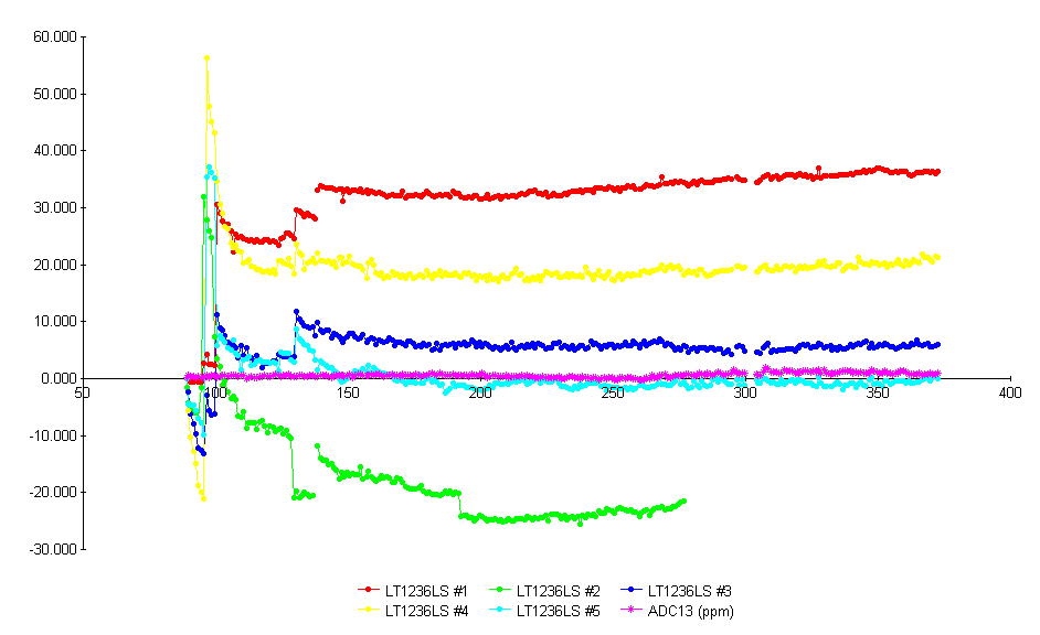


First I have to explain what happens.
I have several references running 24/7 within a thermal box. Each day the pcb is heated from around 35-40 °C (self heating temperature of the references at 20-25 degrees room temperature) to 50 +/- 0.2 degrees. After heating up all Gnd-Pins of the references are measured with my best ADC (there is a up to 60uV shift between them due to the supply currents) and after this all output pins are measured and the difference between output and gnd pin is recorded and the drift is calculated.

The ADC#13 which is used together with a 2:1 LTC1043 based voltage divider finally measures his own offset and a high stable LTZ1000 reference. And also this drift value is recorded on the sheet. So if you would want to exclude the drift of the adc and the voltage divider you would have to subtract the pink ADC13 curve from the reference curves.

Measurement starts at DAY89 when I put the 5 references into the temperature box.
Reference #1 had already 2 temperature cycles from around 10 - 45 °C for TC measurement at this day. So #1 was already running for 1 week.
For the other references I did the TC measurements after DAY89. Which can be seen as "shift" in their ageing curve.
As I mentioned relatively large hysteresis shifts I tried if they could be removed by some "thermal handling" so at day 100 I put all 5 references into the freezer (-18 °C) and warmed them up with a hair dryer several times. At day 130 I repeated thermal handling with #1-#4 and #5 had its TC measurement. Some TC measurements where repeated. Last one was on #2 at day 137. Except on day 192 where I repeated TC measurement for reference #2.

So "shi(f)t" happens as you can see on every "event" in life of the references. Every event starts a new ageing cycle. Either with a lower or a higher drift rate. The large drift rates after the events can be approximated by some sqrt-function. Whereas the final drifts after some thousand hours seem to drift randomly. (or perhaps my measurement system is not good engough).

The 2nd picture shows the same beginning from day 138 (approximately after 1200 hours from the begin).


Compared to other devices the LT1236 have larger hysteresis so it would be better not to heat them up every day but leave them at constant temperature. But since I'm still looking for the perfect non heated reference for battery supply with minimum power requirements I will not change my measurement conditions.

With best regards

Andreas


« Last Edit: August 04, 2013, 09:44:01 pm by Andreas »
 

Offline dfmischler

  • Frequent Contributor
  • **
  • Posts: 548
  • Country: us
Re: thought experiment - self-controlled voltage reference
« Reply #65 on: August 05, 2013, 10:48:20 am »
Attached some measurement data of 5 LT1236AILS8-5 buried zener references.

I couldn't find an explicit description in your post of the values on your graph axes.  Not being clairvoyant, I thought I would ask.

It seems clear that the X-axis values in your graphs represent days.  Are you taking one sample per day?  Multiple samples per day?  If multiple samples, how are you combining them?

Are the Y-axis values in ppm?  ppm / sqrt(khr)?  Or what?
 

Offline branadicTopic starter

  • Super Contributor
  • ***
  • Posts: 2452
  • Country: de
  • Sounds like noise
Re: thought experiment - self-controlled voltage reference
« Reply #66 on: August 05, 2013, 11:02:00 am »
The question is related to Andreas, but I answer right now ;)

x-axis represents time in hours.
y-axis is the normalized value in ppm, normalized because they all start with 0ppm deviation at "day 0".
Computers exist to solve problems that we wouldn't have without them. AI exists to answer questions, we wouldn't ask without it.
 

alm

  • Guest
Re: thought experiment - self-controlled voltage reference
« Reply #67 on: August 05, 2013, 11:57:14 am »
What I think is nice in the LT1236LS8 datasheet graph is that they normalized the curves at t = 100 h. This skips the large initial drift, so the curves are closer together and it's easier to compare small changes between the curves.
 

Offline Andreas

  • Super Contributor
  • ***
  • Posts: 3311
  • Country: de
Re: thought experiment - self-controlled voltage reference
« Reply #68 on: August 05, 2013, 07:07:40 pm »

I couldn't find an explicit description in your post of the values on your graph axes.  Not being clairvoyant, I thought I would ask.

It seems clear that the X-axis values in your graphs represent days.  Are you taking one sample per day?  Multiple samples per day?  If multiple samples, how are you combining them?

Are the Y-axis values in ppm?  ppm / sqrt(khr)?  Or what?

As you can interpret from the description (DAY89) and from the general description on the plot ADC13 (ppm) X-axis is in days and y-axis is in ppm normalized to start of the measurement. So branadic got it right from the description.
Usually I record 1 sample per day (integration time is 1 minute) the values are all as dot on the measurement connected with lines.

What I think is nice in the LT1236LS8 datasheet graph is that they normalized the curves at t = 100 h. This skips the large initial drift, so the curves are closer together and it's easier to compare small changes between the curves.

In the current data sheet it is normalized to t=10 h. In which version did you see the 100 h?
And 10 h from what time after soldering. And what happened to the board after soldering before start of measurement? Perhaps seveal temperature cycles with decreasing amplitude around 35 degrees?
What means the Therm: "Typical long-term drift is illustrated in Figure 1" in the datasheet? Really measured values or only drawn from mind?

With best regards

Andreas
 

Offline branadicTopic starter

  • Super Contributor
  • ***
  • Posts: 2452
  • Country: de
  • Sounds like noise
Re: thought experiment - self-controlled voltage reference
« Reply #69 on: August 06, 2013, 06:05:04 pm »
I have asked Linear Technology for the data of their long-term stability test. Will be interesting what they will answer.

It's sad that there's no standardized test condition and they don't say more than that the test was made using an 8.5 digit DVM in a "constant?" oven with T=35°C. What about the real temperature and humidity trend, what about the supply voltage while measurement? If everything was really constant than all the common mode behaviour could be due to the DVM and/or the scanner. I doubt that 80 exemplars have the same common mode behaviour. Everything is a bit nebulous.
Computers exist to solve problems that we wouldn't have without them. AI exists to answer questions, we wouldn't ask without it.
 

Offline Andreas

  • Super Contributor
  • ***
  • Posts: 3311
  • Country: de
Re: thought experiment - self-controlled voltage reference
« Reply #70 on: August 30, 2013, 08:11:01 am »
I have asked Linear Technology for the data of their long-term stability test. Will be interesting what they will answer.

Everything is a bit nebulous.

Did you get already a answer.
Usually they reply within a few days.

With best regards

Andreas
 

Offline branadicTopic starter

  • Super Contributor
  • ***
  • Posts: 2452
  • Country: de
  • Sounds like noise
Re: thought experiment - self-controlled voltage reference
« Reply #71 on: September 02, 2013, 08:46:13 am »
Quote
Did you get already a answer.

No, I didn't, obviously they didn't care about my request.
Computers exist to solve problems that we wouldn't have without them. AI exists to answer questions, we wouldn't ask without it.
 

Offline babysitter

  • Frequent Contributor
  • **
  • Posts: 899
  • Country: de
  • pushing silicon at work
Re: thought experiment - self-controlled voltage reference
« Reply #72 on: September 03, 2013, 07:52:37 am »
I guess they figured out that you are one of those precision voltage hobbyists from the eevblog, just with little value for their sales :-DD

I'm not a feature, I'm a bug! ARC DG3HDA
 

Offline branadicTopic starter

  • Super Contributor
  • ***
  • Posts: 2452
  • Country: de
  • Sounds like noise
Re: thought experiment - self-controlled voltage reference
« Reply #73 on: September 03, 2013, 04:08:44 pm »
I can't believe that's the reason, as I settled my request with my offical account from work. And yes, I order LT parts by that account too.
Computers exist to solve problems that we wouldn't have without them. AI exists to answer questions, we wouldn't ask without it.
 

Offline rs20

  • Super Contributor
  • ***
  • Posts: 2322
  • Country: au
Re: thought experiment - self-controlled voltage reference
« Reply #74 on: September 04, 2013, 01:43:58 am »
Just a simple question, because we're getting massively sidetracked by trying to get data for specific parts. The point is, it's absurd to say that a group of three voltage references in close proximity will mystically communicate with each other and ensure that no common-mode-looking drift ever occurs. It's like saying that if you flip three coins, you'll never get three heads because there's no systematic reason why they would all align.

Put in more concrete terms: how are you going to tell the difference between:

Case 1: refs A & B drift up by 10 ppm, ref C drifts down by 5 ppm
and
Case 2: refs A & B drift up by 5 ppm, ref C drifts down by 10 ppm

In both of these cases, A-B=0, B-C=15, C-A=-15, (A+B)/2-C=15, any relative computation you perform will be the same.

Also, how are we five pages into this discussion without a working matlab/octave/excel/python/whatever model? I don't care how you model the drift of the voltage references. No need for part datasheets. The only way you'll get it to work, even theoretically, is if you compute the drift of ref C by calculating it based on ref A and ref B. I.e., cheat. If all three refs are modelled with drift calculated from independent random drift, and you keep all your calculations relative, I suspect you're going to have a great deal of difficulty demonstrating this working even theoretically, beyond the sqrt(3) gain that you can get by just averaging the three references.


Share me

Digg  Facebook  SlashDot  Delicious  Technorati  Twitter  Google  Yahoo
Smf