Author Topic: Solartron 7081 - Reference Circuit  (Read 4038 times)

0 Members and 1 Guest are viewing this topic.

Offline unseenninjaTopic starter

  • Regular Contributor
  • *
  • Posts: 82
  • Country: se
Solartron 7081 - Reference Circuit
« on: July 20, 2024, 12:37:04 am »
I'm slowly losing my mind with the Solartron 7081.

I bought a 'for repair' unit, thinking that the problem wouldn't be significant... I won't bore you with tales of a multimeter which had obviously been dropped at some point in its life. Or the story of inexplicable problems and their solutions. In the end, I managed to get it working again so that I could start testing it.

I checked the 10V range against one of my most stable and quiet references - a Dr. Frank LTZ1000 build. Sadly, what I saw was 4ppm popcorn noise:
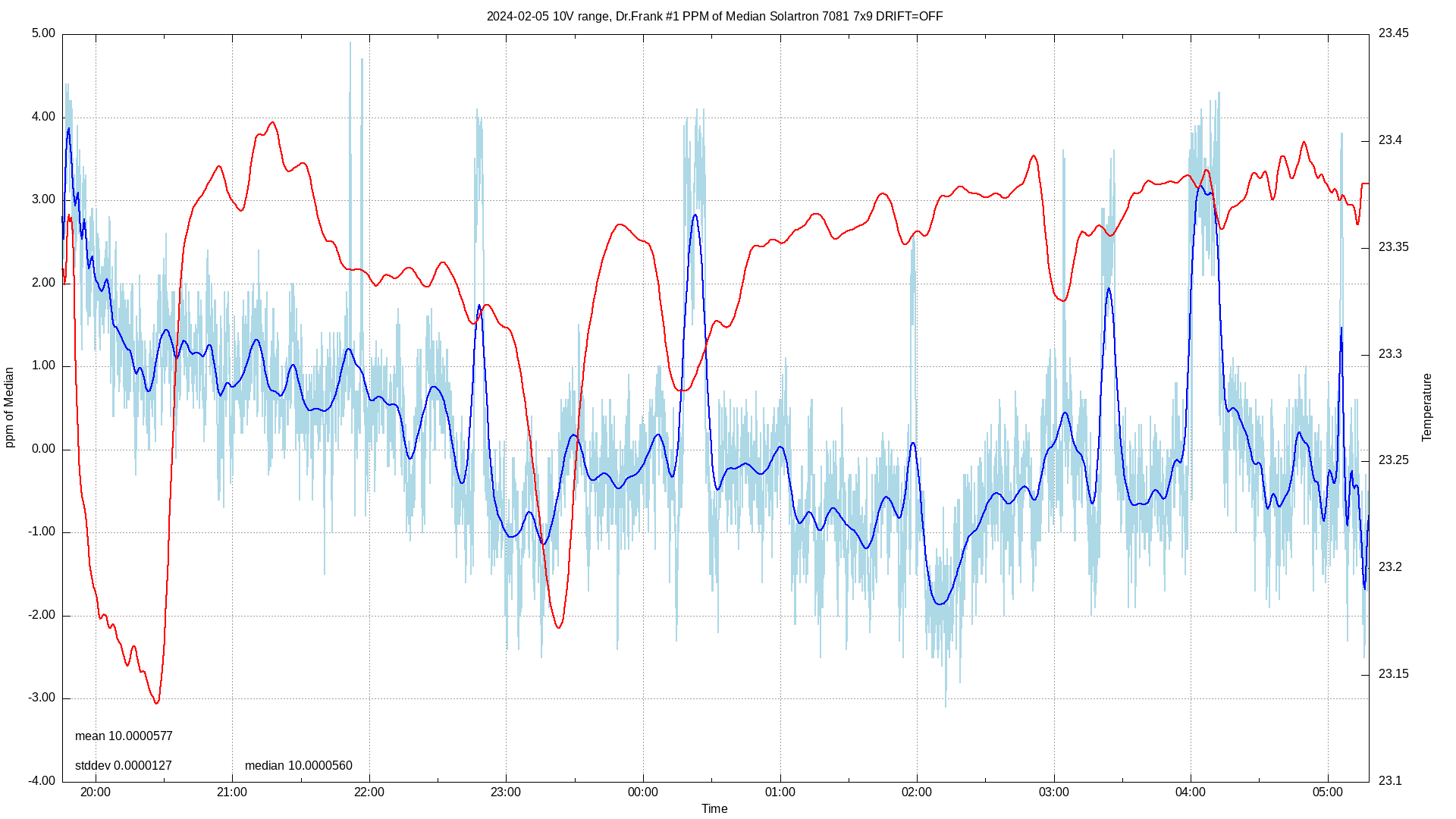


After eliminating every other component in the reference circuitry I was forced to accept that my finely aged and selected by greybeards reference diode had surrendered its ppms and stability.

I know. The answer is "put an LTZ1000 reference in there". That wouldn't be keeping the meter original though, would it? So I found a supplier of new, old stock 1N829 diodes on eBay and threw myself head first into the process of trying to find one golden 1N829 from the six that I'd bought.
I put together my first ever KiCAD project to create a PCB with six 7.5mA current sources, had it made in China, learned about not just double, but triple checking every aspect before committing a design for production, worked around my mistakes and started the selection process.
Two diodes had terrible popcorn noise and were immediately eliminated. The other four had a pair of stars and two which were OK. So I let them age for another 2000 hours... Two of them, according to my Euler Precision LFLNA-80 turned out to have around 0.5µV peak to peak noise.
I took the best one and started ramping it from 39ish°C to 51ish°C at increasing current.

I found a magic current for my best diode!

But here's where my problems start.

If I read the Solartron 7081 service manual, in the description of the reference circuit, it talks about the second order tempco correction circuit being centred around the top of the curve being at 27°C. That makes no sense at all. The average internal temperature of my 7081 is between 40 - 45°C depending on the ambient temperature. This meter is a closed case meter with no fans. There is no way that after being powered up for a day that the internal temperature would ever be even close to 27°C!

I looked at the wonderful document that Mickle T had written about his experiments with the 7081. In there, he talks about how the reference circuit works. Following his documentation, I could easily work out how to set the required "Zener Token" value and adjust the resistors involved so that I could set the correct current for my new diode. That turned out to be 7.8mA:
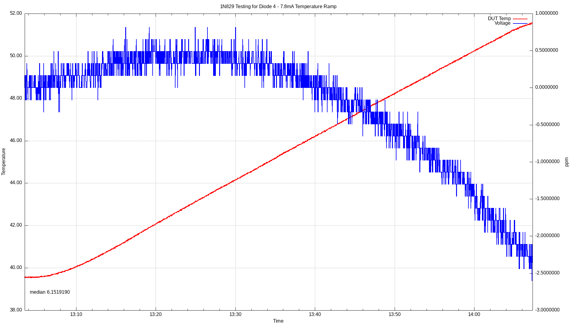


What I can't work out how to do is recalculate the values of resistors R351 and R354. As I now have a current for my diode which places the top of the tempco curve at between 40°C to 45°C - exactly where it needs to be for my meter, I need to know how I can work out what the values of these two resistors should be.

Can anyone help me?
« Last Edit: July 21, 2024, 09:28:36 am by unseenninja »
 

Offline Kleinstein

  • Super Contributor
  • ***
  • Posts: 14842
  • Country: de
Re: Solartron 7081 - Reference Circuit
« Reply #1 on: July 20, 2024, 07:02:16 am »
The square circuit can only work with positive values. R351 sets the offset / zero for the temperature (those odd looking 27° C). One might argue this could be a bit on the low side, but it sets the minimum temperature the ref circuit works.
The exact value is not important, but it also effects the overall linear TC. If really needed it may be used to fine tune the linear TC later, though the main path for this seems to be the DAC part.

R354 (or alternatively also R353) sets the scale for the correction current and thus the T² term in the correction.
Chances are one would first have to adjust the square term via R354 and than do a fine correction of the linear term.


Overall the ref. circuit part looks rather complicated, especially the optocouplers and DAC to be set by jumpers.
 
The following users thanked this post: unseenninja

Offline guenthert

  • Frequent Contributor
  • **
  • Posts: 761
  • Country: de
Re: Solartron 7081 - Reference Circuit
« Reply #2 on: July 20, 2024, 08:06:36 am »
[..]
After eliminating every other component in the reference circuitry I was forced to accept that my finely aged and selected by greybeards reference diode had surrendered its ppms and stability.
I think this deserves some elaboration.  How did you determine that the noise comes from the reference of the DMM and not a different component or the source (the LTZ1000)?  Frankly I'm a bit skeptical that a Zener should develop popcorn noise late in life.

I know. The answer is "put an LTZ1000 reference in there". That wouldn't be keeping the meter original though, would it?
Dunno.  If you intend to keep the unit, it's of course entirely up to you.  If you mean to sell the unit later on, it would be fair to document what you did.  I doubt many would prefer an artisan-made 1N829 based reference over an artisan-made LTZ1000 reference.

So I found a supplier of new, old stock 1N829 diodes on eBay
1N829 or 1N829A?  The former seems to be still easily available (as NOS, e.g. at Anchor Electronics), the latter harder to find and considerably more expensive.  Afaiu the latter are selected for lower tempco.  Not sure if there are other differences or whether there are some 1N829 just as good as 1N829A.

I tinkered a bit with 1N829 and while they perform as specified (specifications I found were 'thin'), I found them too noisy and poor in terms of long term stability to be all that interesting.  I know that HP (in the 735A), Solartron and Datron used 1N825(A?)/1N829(A?) much more successfully, but I suspect they put a lot more effort into the selection process than I could muster the patience for.
 

Online tggzzz

  • Super Contributor
  • ***
  • Posts: 20732
  • Country: gb
  • Numbers, not adjectives
    • Having fun doing more, with less
Re: Solartron 7081 - Reference Circuit
« Reply #3 on: July 20, 2024, 09:27:09 am »
I checked the 10V range against one of my most stable and quiet references - a Dr. Frank LTZ1000 build. Sadly, what I saw was 4ppm popcorn noise:

If you are looking at noise, then measure the voltage of some form of chemical battery. While you will probably see drift as the temperature changes, any noise you see will be within the meter - e.g. the voltage reference diode.

I've used a 7081 with a (1949, still in-spec!) saturated Weston standard cell. While the cell made a reasonable thermometer, it was effectively noiseless.

https://www.eevblog.com/forum/metrology/weston-cells/msg4093978/#msg4093978
There are lies, damned lies, statistics - and ADC/DAC specs.
Glider pilot's aphorism: "there is no substitute for span". Retort: "There is a substitute: skill+imagination. But you can buy span".
Having fun doing more, with less
 

Offline unseenninjaTopic starter

  • Regular Contributor
  • *
  • Posts: 82
  • Country: se
Re: Solartron 7081 - Reference Circuit
« Reply #4 on: July 21, 2024, 09:39:38 am »
I think this deserves some elaboration.  How did you determine that the noise comes from the reference of the DMM and not a different component or the source (the LTZ1000)?  Frankly I'm a bit skeptical that a Zener should develop popcorn noise late in life.

I'm sure that the popcorn noise was coming from the reference Zener. I also have a perfectly quiet and reliable Datron 1271, and my Dr. Frank reference, measured on the 1271 produces a completely acceptable result, changing by around +/- 0.4ppm over temperature excursions of 2°C. It has no popcorn noise.


I was also sceptical that a diode would develop popcorn noise later in life, but after changing every other active component in the reference circuit and checking all the passive components, the only thing left to account for the popcorn noise that I saw was the diode.

1N829 or 1N829A?  The former seems to be still easily available (as NOS, e.g. at Anchor Electronics), the latter harder to find and considerably more expensive.  Afaiu the latter are selected for lower tempco.  Not sure if there are other differences or whether there are some 1N829 just as good as 1N829A.

The difference between the non-A and A version of the 1N829 is the maximum Zener impedance. 15 Ohms for the non-A version and 10 Ohms for the A version.
Both have a data sheet specified tempco of 5ppm/°C at 7.5mA current. My replacement is a 1N829.

The square circuit can only work with positive values. R351 sets the offset / zero for the temperature (those odd looking 27° C). One might argue this could be a bit on the low side, but it sets the minimum temperature the ref circuit works.
The exact value is not important, but it also effects the overall linear TC. If really needed it may be used to fine tune the linear TC later, though the main path for this seems to be the DAC part.

R354 (or alternatively also R353) sets the scale for the correction current and thus the T² term in the correction.
Chances are one would first have to adjust the square term via R354 and than do a fine correction of the linear term.

Overall the ref. circuit part looks rather complicated, especially the optocouplers and DAC to be set by jumpers.


It is indeed complicated. The DAC is set by the firmware based on the value set for what Solartron call the "Zener Token". This determines the voltage generated by the DAC and therefore the current added to that generated by the fixed resistor R304.

From what you are saying, I guess the only thing I can do is implement the calculations that Mickle shows in his document:


I already have a spreadsheet which allows me to calculate the setting of the Zener Token and the value of R304 which is needed. (The Iz(token) part from Mickle's calculation). Then I'll need to implement the rest of his calculations so that I can plot the compensation curve and adjust R351 and R354 until they match the tempco curve that I derived for the diode in testing.

Or, just give in and just put a KX reference in the machine!
 
The following users thanked this post: guenthert

Offline branadic

  • Super Contributor
  • ***
  • Posts: 2448
  • Country: de
  • Sounds like noise
Re: Solartron 7081 - Reference Circuit
« Reply #5 on: July 21, 2024, 09:44:06 am »
Just my two cent on that topic. As the S7081 is a rather noisy meter due to its ADC an ADR1399 reference could be more than sufficient enough.

-branadic-
Computers exist to solve problems that we wouldn't have without them. AI exists to answer questions, we wouldn't ask without it.
 
The following users thanked this post: unseenninja

Offline EC8010

  • Regular Contributor
  • *
  • Posts: 174
  • Country: gb
Re: Solartron 7081 - Reference Circuit
« Reply #6 on: July 21, 2024, 10:25:11 am »
On the subject of popcorn noise, I also think it's unlikely that the Solartron's zener developed popcorn noise later in life - it probably had it from the start. When that meter was made, semiconductor fabs were much muckier than now, so popcorn noise was much more likely. That's not to say you can't find it now - I measured a recent REF102 and found popcorn noise at 1ppm. I also wondered if it could be my DMM (34470A) but an oscilloscope trace via home-made LNA also showed popcorn noise. (And the LNA doesn't have popcorn noise.) I would second batteries as being low noise, or at least, lead-acid and alkaline. I have been told that some lithium batteries are noisy but I've not measured them myself.

Secondly, please could the OP post a link to the MickleT reference? I have a 7075 that is probably similar in principle.

Finally, I met a chap at an amateur radio rally recently who claimed to work "next door" to Solartron and he said that Solartron tested an awful lot of Zeners, grading the very best for their best meters and the rest for their less critical meters. Apocryphal, maybe, but it makes sense - I would have expected to need to test a lot more than just six 1N829 to find a good one. If you bought a few thousand 1N829, you'd need a use for all the duffers.
 

Online tggzzz

  • Super Contributor
  • ***
  • Posts: 20732
  • Country: gb
  • Numbers, not adjectives
    • Having fun doing more, with less
Re: Solartron 7081 - Reference Circuit
« Reply #7 on: July 21, 2024, 10:37:43 am »
Secondly, please could the OP post a link to the MickleT reference? I have a 7075 that is probably similar in principle.

FYI, I have put a readable s7075 manual on BAMA and xDevs: https://www.eevblog.com/forum/repair/solartron-7075-dvm-better-late-than-never/
There are lies, damned lies, statistics - and ADC/DAC specs.
Glider pilot's aphorism: "there is no substitute for span". Retort: "There is a substitute: skill+imagination. But you can buy span".
Having fun doing more, with less
 
The following users thanked this post: coromonadalix, EC8010

Offline unseenninjaTopic starter

  • Regular Contributor
  • *
  • Posts: 82
  • Country: se
Re: Solartron 7081 - Reference Circuit
« Reply #8 on: July 21, 2024, 11:54:32 am »
On the subject of popcorn noise, I also think it's unlikely that the Solartron's zener developed popcorn noise later in life - it probably had it from the start. When that meter was made, semiconductor fabs were much muckier than now, so popcorn noise was much more likely. That's not to say you can't find it now - I measured a recent REF102 and found popcorn noise at 1ppm. I also wondered if it could be my DMM (34470A) but an oscilloscope trace via home-made LNA also showed popcorn noise. (And the LNA doesn't have popcorn noise.) I would second batteries as being low noise, or at least, lead-acid and alkaline. I have been told that some lithium batteries are noisy but I've not measured them myself.

Secondly, please could the OP post a link to the MickleT reference? I have a 7075 that is probably similar in principle.

Finally, I met a chap at an amateur radio rally recently who claimed to work "next door" to Solartron and he said that Solartron tested an awful lot of Zeners, grading the very best for their best meters and the rest for their less critical meters. Apocryphal, maybe, but it makes sense - I would have expected to need to test a lot more than just six 1N829 to find a good one. If you bought a few thousand 1N829, you'd need a use for all the duffers.

You can download a copy of Mickle T's document from my cloud storage here: https://filedn.com/lEDSGUXnO7mp9lWR3BbARrR/7081/MickleT-7081-fixes.pdf

Although the 7075 has an ADC which works in a similar manner to the 7081, the reference circuitry is very different. It uses an oven to keep the Zener diode at a constant temperature and a string of 11 resistors with selection links, plus a 100 Ohm pot to set the exact Zener current needed for the particular diode. There's nothing in Mickle's 7081 document which would be particularly relevant to the 7075.

My 7081 was dropped from a fair height at some point in its life. The stress caused by the sudden stop at the end of the drop was considerable and mechanical stress could be what caused the diode to develop its popcorn noise. It is highly unlikely that it had this popcorn noise from the beginning as it would have never have made it through the selection process to find its way into the 7081 in the first place. Nor would the meter have passed Solartron's final QA procedure.

Your story about how Solartron selected from many diodes is without doubt accurate. My original diode has three different coloured paint dots on it, green, grey, grey, whereas the reference diodes in my 7061 and 7062 meters have a single yellow dot. That would tend to suggest that an initial selection was made to eliminate the noisy diodes and the OK ones for the 7.5 digit meters were just marked with a single dot. The really good ones were then tested for at least three different characteristics before being deemed fit for the 8.5 digit meters.

I'm fully aware that selecting from just six diodes is a shot in the dark, but for the best one of out the original six, I'm seeing less than 0.5µV peak to peak noise on my LNA and a stable, popcorn free voltage after 2000 hours of being powered up. The particular diodes that I found are military spec versions made in 2002 with the full part number printed on the diode being: JX1N829-1 So there's a good chance that these were already selected for better performance than the average 1N829.
 
The following users thanked this post: SeanB, ch_scr, EC8010

Offline EC8010

  • Regular Contributor
  • *
  • Posts: 174
  • Country: gb
Re: Solartron 7081 - Reference Circuit
« Reply #9 on: July 21, 2024, 12:53:00 pm »
Many thanks for the link to Mickle T's document - it was most interesting. Agreed, the reference is entirely different.

I will probably bump into the chap who told me about Solartron selection at next year's radio rally, so I will try to remember to quiz him further.

You did well with your six 1N829.
 

Offline unseenninjaTopic starter

  • Regular Contributor
  • *
  • Posts: 82
  • Country: se
Re: Solartron 7081 - Reference Circuit
« Reply #10 on: July 21, 2024, 01:39:01 pm »
I'm keeping my fingers crossed that I can get it perfectly tuned and the long term drift isn't horrible.

If you do bump into your contact again, I'm sure I'm not the only one who would be interested to hear more about the methods that Solartron used to find their golden diodes and what characteristics they were testing for.

I have a 7075 myself which is in desperate need of calibration. It was quite badly broken when I received it, but I managed to source new display units to replace the broken ones and get it working again. You just can't beat gas discharge displays!
 

Offline EC8010

  • Regular Contributor
  • *
  • Posts: 174
  • Country: gb
Re: Solartron 7081 - Reference Circuit
« Reply #11 on: July 21, 2024, 04:13:26 pm »
My 7075 has enormous amber 7 segment LEDs behind a neutral density filter, and the resulting display is beautiful - it was what made me buy it. 7075 is presently in pieces as I've replaced that inconvenient Fischer connector with a pair of low thermal EMF binding posts for the sense inputs and three 4mm sockets for the two force outputs and guard output. All of that took up a lot of room and I haven't quite worked out where I can put the "zero" control...

If I do find out any more about Solartron's zener selection, I will post it here.
 

Online tggzzz

  • Super Contributor
  • ***
  • Posts: 20732
  • Country: gb
  • Numbers, not adjectives
    • Having fun doing more, with less
Re: Solartron 7081 - Reference Circuit
« Reply #12 on: July 21, 2024, 05:03:07 pm »
My 7075 has enormous amber 7 segment LEDs behind a neutral density filter, and the resulting display is beautiful - it was what made me buy it. 7075 is presently in pieces as I've replaced that inconvenient Fischer connector with a pair of low thermal EMF binding posts for the sense inputs and three 4mm sockets for the two force outputs and guard output. All of that took up a lot of room and I haven't quite worked out where I can put the "zero" control...

If I do find out any more about Solartron's zener selection, I will post it here.

Are you sure they are LEDs? Panaplex were the original delicious orange displays. Quick test: touch the wrong point on the display panel, and feel the warmth of 180V :)
There are lies, damned lies, statistics - and ADC/DAC specs.
Glider pilot's aphorism: "there is no substitute for span". Retort: "There is a substitute: skill+imagination. But you can buy span".
Having fun doing more, with less
 

Offline EC8010

  • Regular Contributor
  • *
  • Posts: 174
  • Country: gb
Re: Solartron 7081 - Reference Circuit
« Reply #13 on: July 21, 2024, 07:43:54 pm »
Good grief! They looked like a duck, quacked like a duck, but on close inspection, they're not a duck! I'll pass on the 180V suggestion, thank you. If they were seven segment LEDs, they'd be individual for each digit, and they're not. But it is a truly beautiful display and the rest of meter is in lovely cosmetic order, so I'm taking a great deal of care over my connector conversion.
 

Online tggzzz

  • Super Contributor
  • ***
  • Posts: 20732
  • Country: gb
  • Numbers, not adjectives
    • Having fun doing more, with less
Re: Solartron 7081 - Reference Circuit
« Reply #14 on: July 21, 2024, 08:20:56 pm »
Good grief! They looked like a duck, quacked like a duck, but on close inspection, they're not a duck! I'll pass on the 180V suggestion, thank you. If they were seven segment LEDs, they'd be individual for each digit, and they're not. But it is a truly beautiful display and the rest of meter is in lovely cosmetic order, so I'm taking a great deal of care over my connector conversion.

:)

The Big Clue was that you noted they were beautiful to look at. LEDs, with the notable exception of the mid-70s HP "dotted" 7 segment LEDs, are never as pleasing to the eye.

Now you can be on the lookout for Panaplex calculators, nixie counters/DVMs, and dekatron counters. After that you can move onto even weirder wonderful display technologies :)
There are lies, damned lies, statistics - and ADC/DAC specs.
Glider pilot's aphorism: "there is no substitute for span". Retort: "There is a substitute: skill+imagination. But you can buy span".
Having fun doing more, with less
 
The following users thanked this post: unseenninja

Offline unseenninjaTopic starter

  • Regular Contributor
  • *
  • Posts: 82
  • Country: se
Re: Solartron 7081 - Reference Circuit
« Reply #15 on: July 22, 2024, 07:59:24 am »
My 7075 has enormous amber 7 segment LEDs behind a neutral density filter, and the resulting display is beautiful - it was what made me buy it. 7075 is presently in pieces as I've replaced that inconvenient Fischer connector with a pair of low thermal EMF binding posts for the sense inputs and three 4mm sockets for the two force outputs and guard output. All of that took up a lot of room and I haven't quite worked out where I can put the "zero" control...

You may not know, but there is now a source of Fischer connectors with a sensible price and good availability.


Possibly too late if you've already butchered the front of the meter...
 
The following users thanked this post: EC8010

Offline EC8010

  • Regular Contributor
  • *
  • Posts: 174
  • Country: gb
Re: Solartron 7081 - Reference Circuit
« Reply #16 on: July 22, 2024, 10:38:10 am »
Thanks for the information. Sadly, previous owner had replaced the Fischer connector with a 240 degree 5 pin Tuchel, so I don't have the original (presumed faulty) socket. To be fair, he had done his best and he warned me of the new connector's potential limitations, but he didn't have access to a machine shop to do an undetectable job, so I already have a little tidying to do on the Trefolite and its backing panel.
 

Offline Ismsanmar

  • Contributor
  • Posts: 49
  • Country: es
Re: Solartron 7081 - Reference Circuit
« Reply #17 on: July 22, 2024, 10:43:16 am »
My 7075 has enormous amber 7 segment LEDs behind a neutral density filter, and the resulting display is beautiful - it was what made me buy it. 7075 is presently in pieces as I've replaced that inconvenient Fischer connector with a pair of low thermal EMF binding posts for the sense inputs and three 4mm sockets for the two force outputs and guard output. All of that took up a lot of room and I haven't quite worked out where I can put the "zero" control...

You may not know, but there is now a source of Fischer connectors with a sensible price and good availability.


Possibly too late if you've already butchered the front of the meter...
But those are not original Fischer plugs, those are chinese countefeits. And I think that the original ones are custom ordered by Solartron with the insulating materia made of teflon instead of PEEK.

This last I'm not sure because I don't have an original cable, but taking into account that the material used on the receptacle mounted on the meter is made of teflon, the plug should have the same.
 

Offline unseenninjaTopic starter

  • Regular Contributor
  • *
  • Posts: 82
  • Country: se
Re: Solartron 7081 - Reference Circuit
« Reply #18 on: July 22, 2024, 11:50:20 am »
They are indeed Chinese copies, and yes, the insulator is PEEK rather than Teflon.

But, PEEK is perfectly adequate, unless you are making cables for an electrometer, and given the fact that getting hold of the original connectors from Fischer is next to impossible and horribly expensive, the choices would appear to be: butcher the meter and get rid of the Fischer connectors or buy well made copies from China.

Given that Fischer seem not to care about hobbyists needing to find spare parts for their Solartron equipment, I'm more than happy to buy from a Chinese manufacturer who has seen the gap in the market and makes very well machined and finished copies.
 

Offline EC8010

  • Regular Contributor
  • *
  • Posts: 174
  • Country: gb
Re: Solartron 7081 - Reference Circuit
« Reply #19 on: July 22, 2024, 12:38:01 pm »
Since the subject of electrometers and PTFE has been brought up, I should point out that PTFE is not the ideal insulating material when electrometers and little currents are involved. PTFE is triboelectric (scraping on a conductor induces a charge) and piezoelectric (mechanical stress induces a charge). Further, PTFE has a phase change at 19C that causes a change in volume, so if it's constrained, that provokes a charge. A colleague told me about one of his electrometers that had a barbed feed through pin in PTFE that behaved oddly and it took him some time to pin it down to the constrained PTFE and phase change with temperature. Clear perspex is the best stuff for diddy currents.

As far as the Solartron is concerned, PEEK will be just fine.
 
The following users thanked this post: ch_scr, unseenninja

Offline unseenninjaTopic starter

  • Regular Contributor
  • *
  • Posts: 82
  • Country: se
Re: Solartron 7081 - Reference Circuit
« Reply #20 on: July 22, 2024, 01:05:51 pm »
Since the subject of electrometers and PTFE has been brought up, I should point out that PTFE is not the ideal insulating material when electrometers and little currents are involved. PTFE is triboelectric (scraping on a conductor induces a charge) and piezoelectric (mechanical stress induces a charge). Further, PTFE has a phase change at 19C that causes a change in volume, so if it's constrained, that provokes a charge. A colleague told me about one of his electrometers that had a barbed feed through pin in PTFE that behaved oddly and it took him some time to pin it down to the constrained PTFE and phase change with temperature. Clear perspex is the best stuff for diddy currents.

As far as the Solartron is concerned, PEEK will be just fine.

Yes, I noticed the various drawbacks with PTFE's charge generation capabilities when building cables and fixtures for my Keithley 617. The change in volume at 19°C was not something I knew about, so thanks for that interesting piece of information!

The lesser Solartron meters (7062, etc) actually use PEEK in their genuine Fischer connectors and although PTFE has a few orders of magnitude higher resistance than PEEK, even worst case, PEEK still has 1015 Ohms/cm. As you say, just fine for any of the Solartron meters.
 

Offline Ismsanmar

  • Contributor
  • Posts: 49
  • Country: es
Re: Solartron 7081 - Reference Circuit
« Reply #21 on: July 22, 2024, 03:26:22 pm »
They are indeed Chinese copies, and yes, the insulator is PEEK rather than Teflon.

But, PEEK is perfectly adequate, unless you are making cables for an electrometer, and given the fact that getting hold of the original connectors from Fischer is next to impossible and horribly expensive, the choices would appear to be: butcher the meter and get rid of the Fischer connectors or buy well made copies from China.

Given that Fischer seem not to care about hobbyists needing to find spare parts for their Solartron equipment, I'm more than happy to buy from a Chinese manufacturer who has seen the gap in the market and makes very well machined and finished copies.

What I'm triyin to say is that taking into account how much they cost, going for 30-35€ on Aliexpress, they are not so much less than the last price seen for the original ones:
https://www.eevblog.com/forum/buysellwanted/group-buy-fischer-connector-plug-s104-a053-130/
And this order was made with the option that Fisher offer to the public, with PEEK insulation.

Don't get me wrong. I've bough one of the chinese short version to check how well they are made, and they are ok. They use the same metals, finishes and coatings than the original, but I have some other Fischer connectors and you can feel the difference. Of course, I paid for 1 unit 6€ with coupons and discounts on Aliexpress on the last summer sale, but at their original asking price, they are not worth it.

Since the subject of electrometers and PTFE has been brought up, I should point out that PTFE is not the ideal insulating material when electrometers and little currents are involved. PTFE is triboelectric (scraping on a conductor induces a charge) and piezoelectric (mechanical stress induces a charge). Further, PTFE has a phase change at 19C that causes a change in volume, so if it's constrained, that provokes a charge. A colleague told me about one of his electrometers that had a barbed feed through pin in PTFE that behaved oddly and it took him some time to pin it down to the constrained PTFE and phase change with temperature. Clear perspex is the best stuff for diddy currents.

As far as the Solartron is concerned, PEEK will be just fine.

Everybody that has an electrometer should know that that's not exactly correct. Before I bought mine (Advantest R8340A) I searched information to make my own cables, because the unit that I wanted to buy didn't have any test cables. Here in this forum there are some very good threads on that topic, and at the end if you want to go the "low noise" route, always use the original cables, or those relatively cheap triaxial cables made by keithley (new or used) that are always available on eBay, or use Lemo 001 101. And all of those use PTFE in one or two of the insulating sheaths. The magic resides in the carbon layer.

And don't ask me why, but inside every 8.5 digit multimeter that I know, the connection between the binding posts and the pcb is made with a PTFE coated cable.

I was lucky to find a brand new original triaxial cable for the meter (with both internal insulation sheaths made of PTFE), so in the end all good.
« Last Edit: July 22, 2024, 03:57:28 pm by Ismsanmar »
 

Offline EC8010

  • Regular Contributor
  • *
  • Posts: 174
  • Country: gb
Re: Solartron 7081 - Reference Circuit
« Reply #22 on: July 22, 2024, 05:21:41 pm »
All of my statements were factually correct and easily verified. PTFE is an excellent insulator/dielectric when you go up in frequency, having lower losses than most other dielectrics, but that is irrelevant to an electrometer that operates at near-DC. Yes, the carbon layer in commercial electrometer cables tames tribolectricity, but that triboelectricity was a problem introduced by the PTFE.

PTFE insulated cable is popular for a number of reasons. The best justification is that it withstands high temperatures, which is great if you need to move soldered wires. With care, a wire can be desoldered, soldered somewhere else, then resoldered in its original position and provided you deflux afterwards, nobody will be any the wiser. Try that with any other insulator and shrink-back will make your interference obvious. I like PTFE for that property. But we should not be blind to PTFE's documented shortcomings. Just because it is popular does not make it ideal.


Offline Alex Nikitin

  • Super Contributor
  • ***
  • Posts: 1315
  • Country: gb
  • Femtoampnut and Tapehead.
    • A.N.T. Audio
Re: Solartron 7081 - Reference Circuit
« Reply #23 on: July 22, 2024, 05:47:28 pm »
My two cents: at room temperatures as in a lab, I prefer a quality polyethylene isolated triaxial cable (H&S) for my electrometer interconnects. I also had some good experience using PEEK isolated connectors for an electrometer input (PTFE was impossible to use in that particular application) and as long as the temperature is kept below 40-50C they work fine with no reduction in performance compared to PTFE isolated connectors, with sub-fA leakages. 

Cheers

Alex


Offline Ismsanmar

  • Contributor
  • Posts: 49
  • Country: es
Re: Solartron 7081 - Reference Circuit
« Reply #24 on: July 22, 2024, 05:52:26 pm »
All of my statements were factually correct and easily verified. PTFE is an excellent insulator/dielectric when you go up in frequency, having lower losses than most other dielectrics, but that is irrelevant to an electrometer that operates at near-DC. Yes, the carbon layer in commercial electrometer cables tames tribolectricity, but that triboelectricity was a problem introduced by the PTFE.

PTFE insulated cable is popular for a number of reasons. The best justification is that it withstands high temperatures, which is great if you need to move soldered wires. With care, a wire can be desoldered, soldered somewhere else, then resoldered in its original position and provided you deflux afterwards, nobody will be any the wiser. Try that with any other insulator and shrink-back will make your interference obvious. I like PTFE for that property. But we should not be blind to PTFE's documented shortcomings. Just because it is popular does not make it ideal.


Remember that exist something called silicone wire, it doesn't shrink with heat, and that is used to insulate cables. Or kapton coated wire.

It's only used because is the best dielectric, anything more.
 
The following users thanked this post: Mickle T.


Share me

Digg  Facebook  SlashDot  Delicious  Technorati  Twitter  Google  Yahoo
Smf