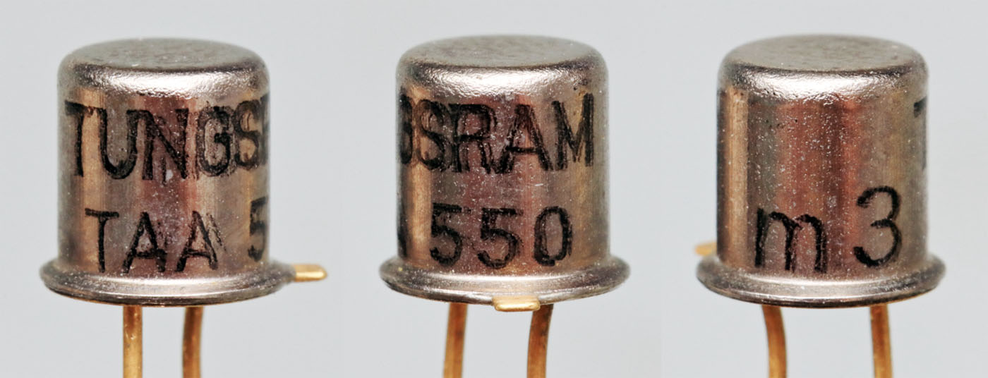
Ignore the MAA550 we had there will be an update soon. Here we have some new insights starting with a TAA550 from Tungsram. The development goes back to Valvo. One of the first advertisements promoting the TAA550 can be found in the magazine Electronics in December 1968. The TAA550 has been copied by many manufacturers over the years.

The application you can see here is taken from the "Philips Data handbook - Semiconductors and integrated circuits" published in March 1977. The filtering of the output is interesting. A CRC circuit is recommended instead of a simple capacitor. In an article in the magazine Electronics (December 1969), Valvo warns you shouldn´t connecting capacitors with more than 4,7nF directly to the output of the TAA550. Otherwise, in the event of a short circuit, oscillations between the line inductance and the capacitor must be expected, the negative voltages of which will damage the TAA550.
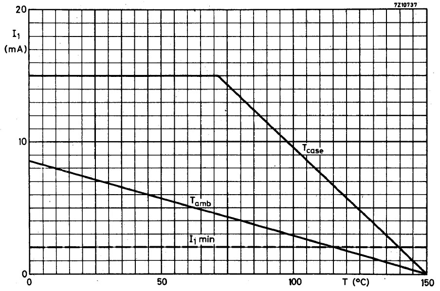
Due to the high reference voltage, the power dissipation that occurs in the TAA550 is not insignificant. The minimum required operating current is 2mA, 5mA is specified as a typical value. With this current, up to 175mW is generated. The datasheet shows that the typical current without heat sink is only permissible up to an ambient temperature of about 60°C.
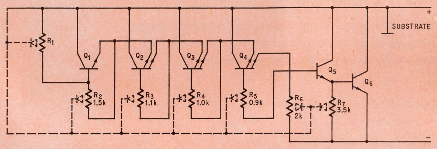
In the magazine Electronics from December 1969 (Volume 42) there is an article in which Valvo describes the construction and the functionality of the TAA550. There is also the above schematic shown, which at first sight seems very confusing.
An obvious and unusual feature of the TAA550 is the fact that the substrate is connected to the positive supply potential. Apart from special exceptions, integrated circuits in bipolar technology have actually always had the substrate connected to the most negative potential of the circuit.
The resistors are drawn with their parasitic diodes. In normal operation, these never become conductive. In the short circuit case described at the beginning, however, they are critical. Already at -1V at the TAA550 one has to expect high currents across the diodes.
The circuit contains three transistors with two emitters each. The functionality is not readily apparent with this illustration.
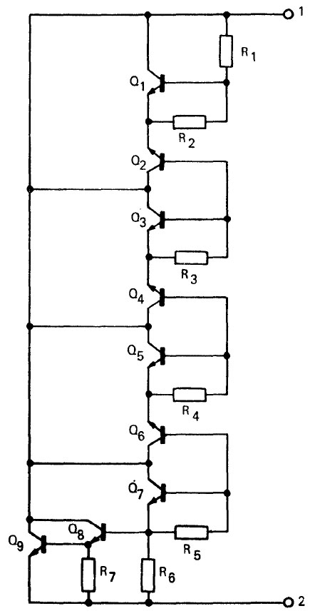
The above schematic is from the 1975/1976 SGS ATES Databook. Transistors Q8 and Q9 represent a Darlington circuit that adjusts the reference voltage by allowing more or less current to flow through the device. The reference voltage is the result of all base-emitter and emitter-base voltages of the circuit. Here, the transistors with the two emitters are each shown as two individual transistors. In one, the base-emitter path is operated in the flux direction (Q3, Q5, Q7), and in the other, it is operated in the reverse direction, acting as a Z-diode (Q2, Q4, Q6).
The transistor Q1 forms a so-called "Vbe multiplier" with the surrounding resistors. The circuit multiplies the base-emitter voltage so that about 1,9V drops across it. The voltage drop across the Darlington output stage is about 1,3V. The voltage drop across transistors Q3, Q5, Q7 is about 2,0V. Thus, the Z-diodes must have Zener voltages in the range of 8,3V to 10V. This is consistent with the article in magazine Electronics, where Valvo specifies an emitter-base breakdown voltage of 8-10V as a target.
As with many reference voltage sources, the positive temperature coefficient of the Z-diodes in the TAA550 is balanced by the negative temperature coefficient of pn junctions conducting in forward direction. However, the high reference voltage requires the somewhat more complex circuit.
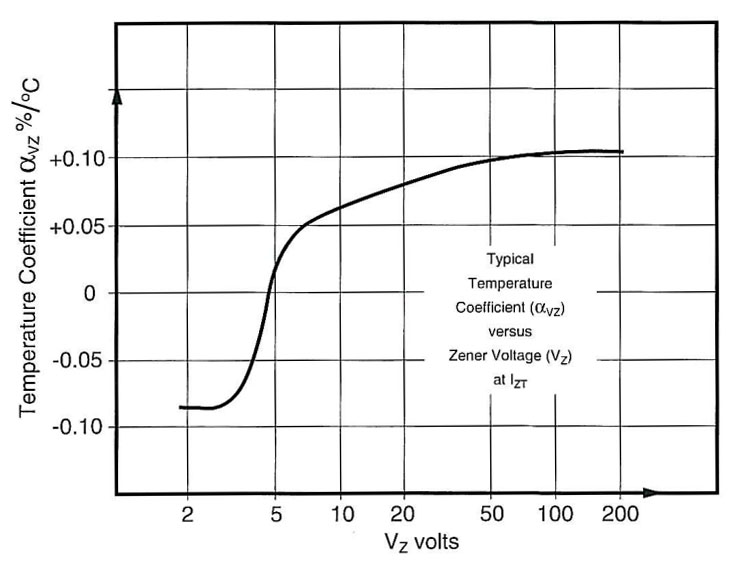
The temperature coefficient of a Z-diode depends on its Zener voltage. Microsemi shows the above behavior in its Micro Notes (203). From a Zener voltage of about 5V, the value becomes positive, whereby the temperature coefficient in this transition range also depends very strongly on the current. At 8-10V one would have to calculate with 0,055-0,065%/K (4,4-6,5mV/K). Assuming that the Z-diodes in the TAA550 behave similarly, they should bring a temperature drift of 13,2-19,5mV/K in total.
A single pn junction, on the other hand, offers a temperature coefficient of just -2mV/K. For this reason, in addition to the Darlington transistors Q8 and Q9, the circuit also contains the transistors Q3, Q5, Q7 working as diodes. This results in a total value of -10mV/K. The missing contribution is provided by the Vbe multiplier around Q1. It multiplies not only the base-emitter voltage itself, but also its temperature coefficients. With the previous estimation, the multiplier should be 1,6-4,8.
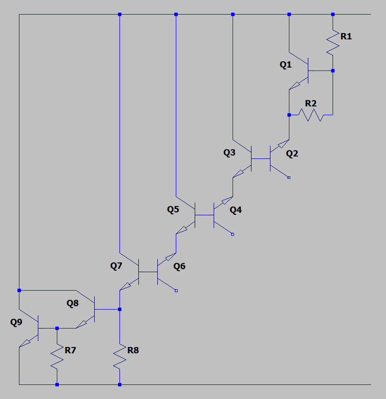
The purpose of the three R3, R4, R5 is not obvious at first glance. They are necessary because the special design of the TAA550 can lead to a problematic behavior. This becomes clearer if the circuit is drawn a little differently and simplified. Here you can see that the transistors Q3, Q5 and Q7 have the potential to behave like a chain of Darlington transistors. The current flow through the collectors would cause the transistors to saturate and there would be no longer a useful reference voltage.
To prevent this, resistors R3, R3 and R5 have been integrated. They sink the collector current and thus prevent it from becoming effective in the base-emitter junction. As the collector-base voltage and thus also the collector current increase downwards, the values of the resistors become smaller: 1,1kΩ / 1kΩ / 0,9kΩ.
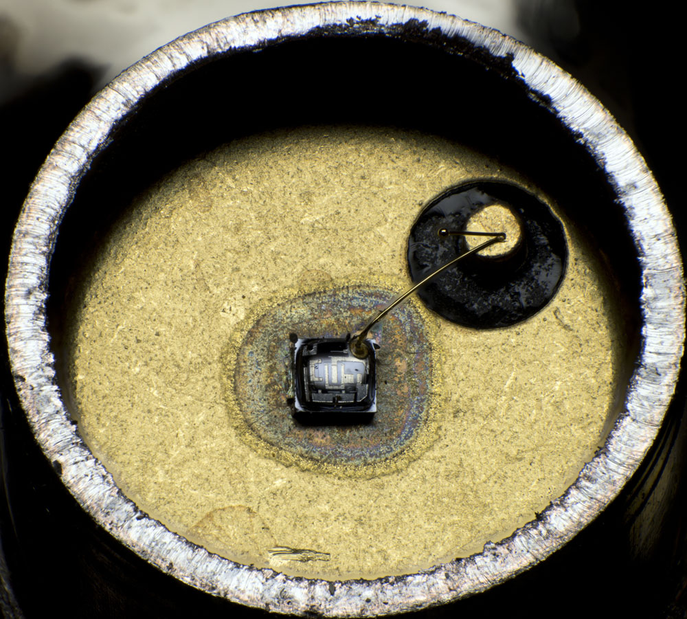
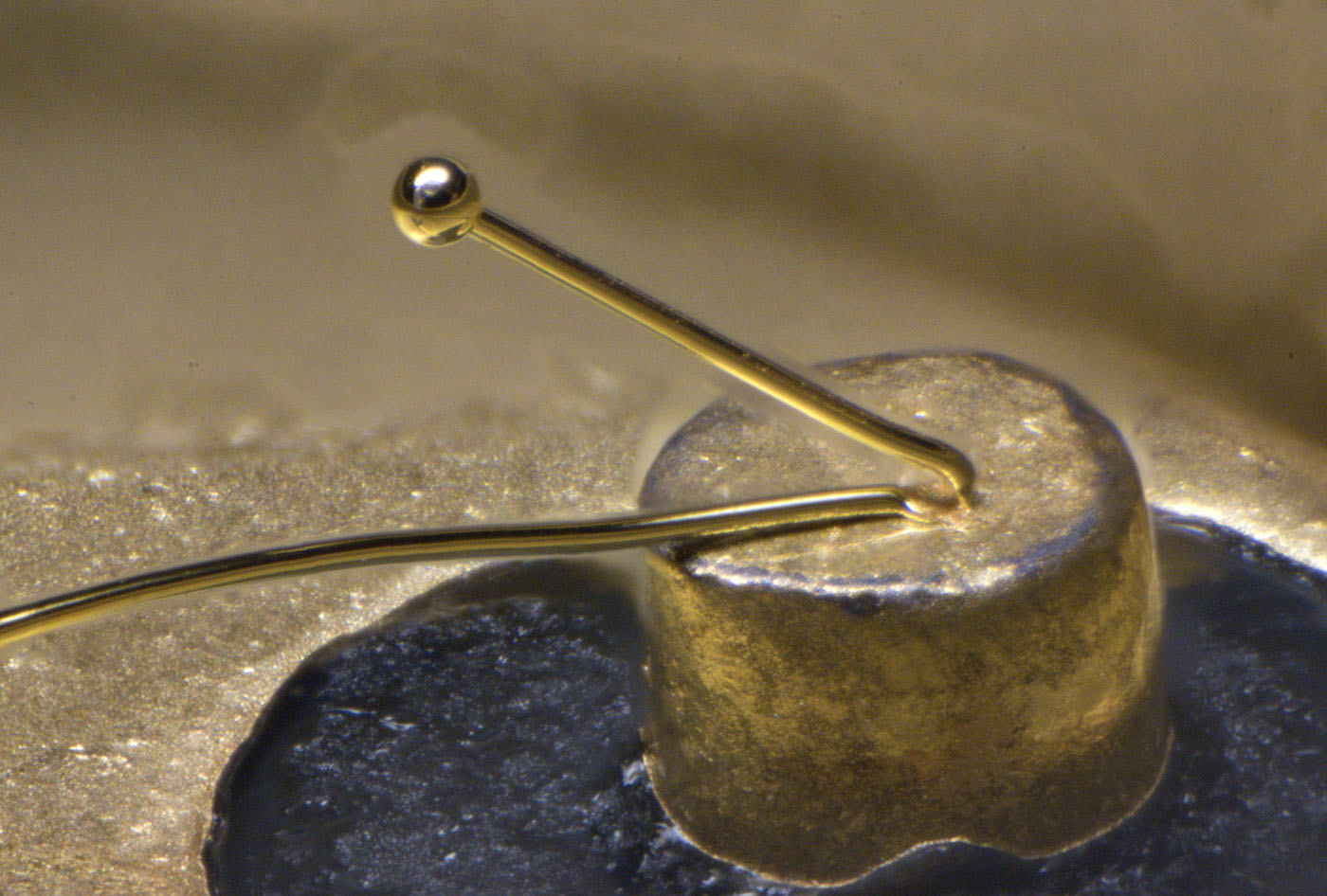
Here you can see the inside of the package. The end of the bondwire is strange. They left it quite long ending with a molten ball.
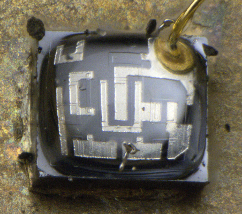
A transparent potting protects the die from environmental influences. It can be dissolved with paint stripper and then removed.
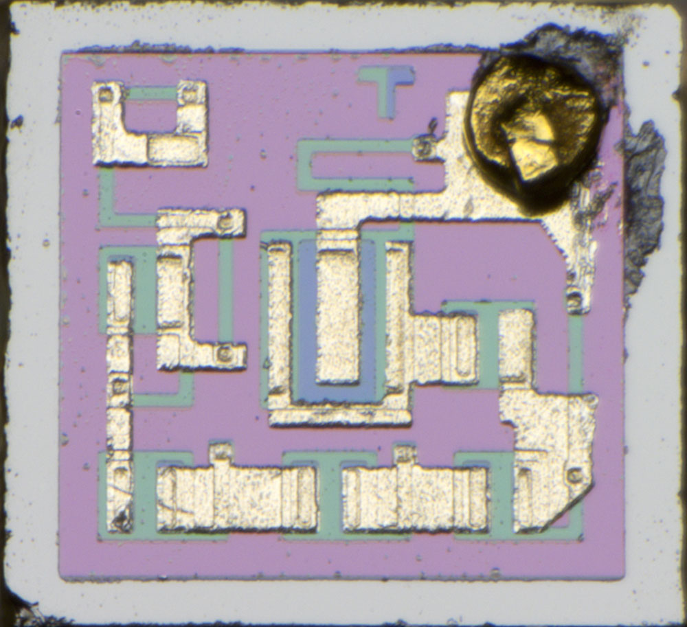
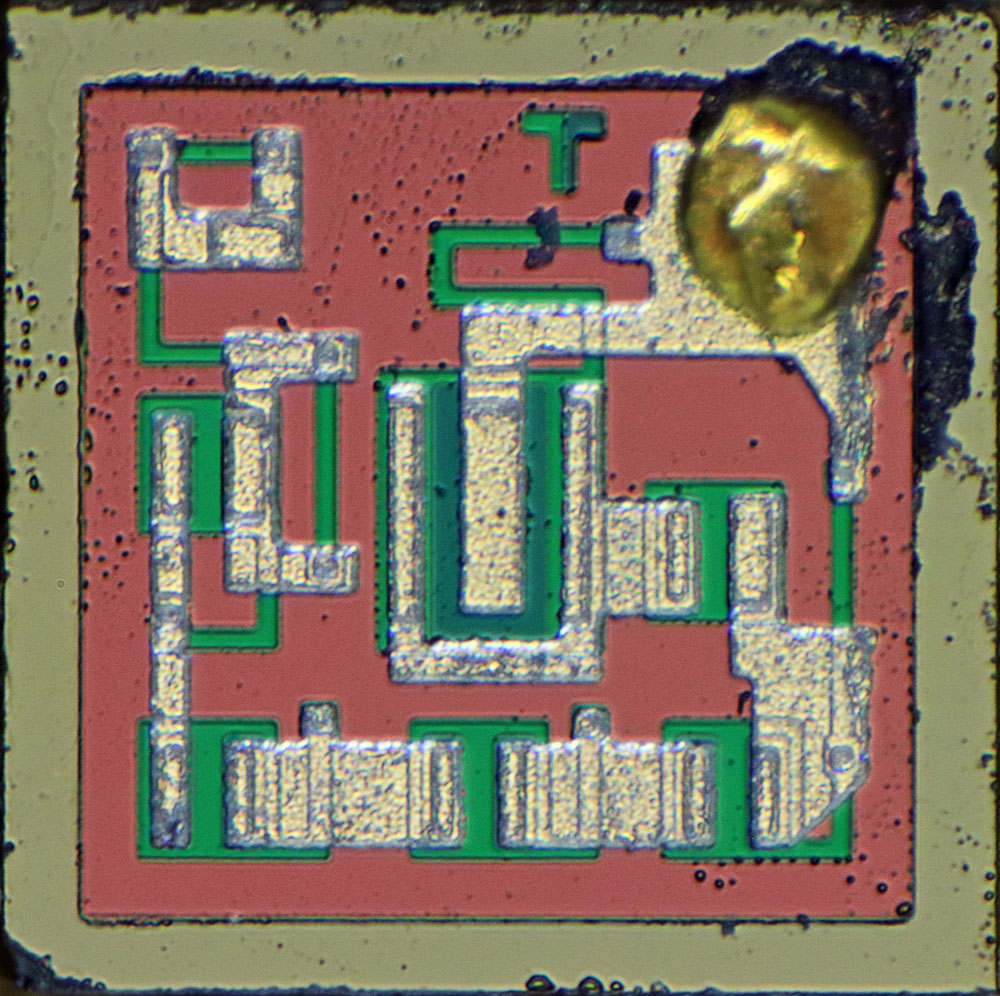
The edge length of the die is 0,55mm. Next to the bondpad is a T like Tungsram used as a logo. The typical dichotomy was implemented with the base and emitter doping. As a side effect, you can use the logo to see how well the two masks are aligned with each other.
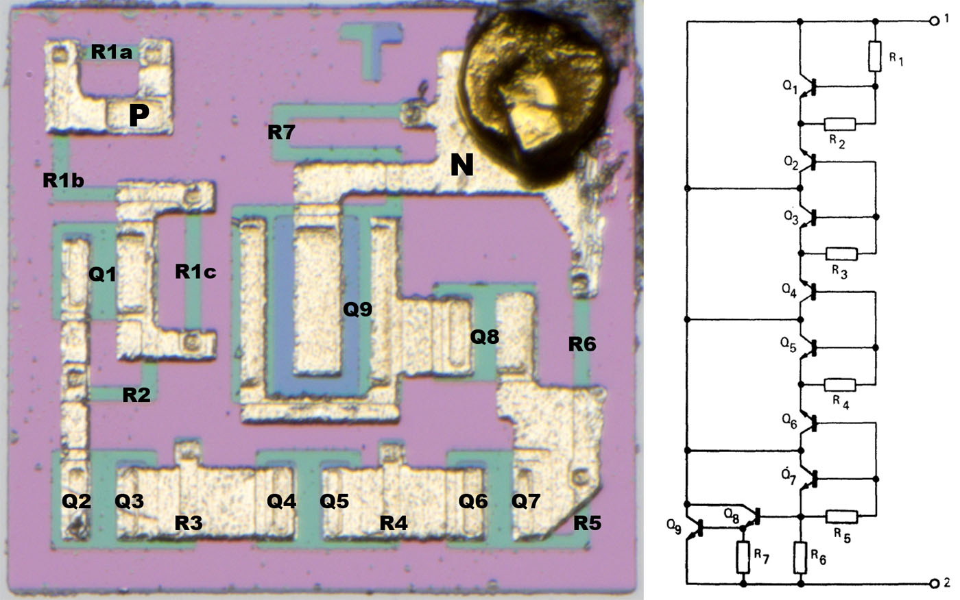
The most striking feature of TAA550 is the absence of isolated wells. All elements are located in the n-doped substrate. For this reason, the substrate here is connected to the positive supply potential via the package. In the upper left corner of the die is where the positive supply potential is fed into the circuit.
Q1, Q8 and Q9 are constructed like normal transistors except for the missing isolation to the substrate. The other transistors each have two blue emitter areas in the green base area. This can be seen especially well with the double transistor Q4/Q5. The output stage transistor Q9 is much larger to show a sufficient current carrying capacity.
The resistors R3 and R4 appear to be similar in size. R5, on the other hand, is noticeably smaller.
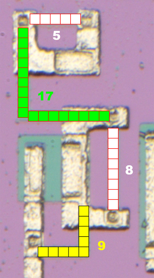
The resistor R1 consists of three elements. Depending on which multiplier you need for transistor Q1, you can bridge the resistors by changing the metal layer. However, this is not an individual tuning of one part. The manufacturing process must be stable enough that once the temperature coefficient has been set, it remains sufficiently constant through the batch. Roughly estimated, the multiplier can be adjustable in the range between 1,6 and 4,3. In this TAA550, the factor is something around 2,9, which seems plausible.
https://www.richis-lab.de/REF36.htm 