Author Topic: Is the quest of replicating a Datron 470x calibrator totally foolish or crazy ?  (Read 22122 times)

0 Members and 1 Guest are viewing this topic.

Offline DC1MCTopic starter

  • Super Contributor
  • ***
  • Posts: 1882
  • Country: de
Well somehow getting bored of trying to find a V/I/R calibrator of reasonable cost and weight  ;D, I was browsing the almost unreadable scans of some Datrons 4707/4708 and looked firs at the digital part, that I found to be really naive, even for the time, and also I've had a look at the analogue part and, while complex, it didn't seem so magically unreproducible, hell, even the original transistors used in the original chopper along with the most other components are still available as NOS. Nothing like the Ferrenti unobtaniums form the Datron multimeters.

If I'm not missing something ultra-obvious, I think that at least the low voltage part should be replicable with the current technologies and components for not too much money, and in the worst case I'll make a precision power supply out of it or at least gain some experience   ^-^.

Now of course, everybody knows that something is not possible, until some fool doesn't know and tries, what are you saying, did someone already tried it, any experiences, advice and stuff are welcome.

Or else I'll have to make a big dent in my X-mas bonus with this guy:
https://www.ebay.de/itm/Kalibrator-Datron-4000-DC-Kalibrator-Spannung-Stromstärke-Widerstand/401619940787

 Cheers,
 DC1MC
 

Online Echo88

  • Frequent Contributor
  • **
  • Posts: 844
  • Country: de
Assuming the Datron uses a PWM-DAC: Its not the problem to replicate the pcb of such calibrators like the Datron or a Fluke 5700A.
Its just an insane amount of work to replicate them/characterise them and in the end you will spend more time and money on rebuilding something that can be bought used and with known specs.
I still have a Fluke 5700A PWM-DAC PCB which i wanted to use as a high-precision +-10V DAC, but invested my time in other projects. You can buy the PCB from me and use that as a starting point.
Lets take a look at another piece of equipment nobody has yet copied (AFAIK), despite it being relatively simple: the Datron 4910.
 

Offline Kleinstein

  • Super Contributor
  • ***
  • Posts: 14671
  • Country: de
There is one important part that is difficult to copy: that is a proven track record of reliability.

The digital part is expected to be relatively simple, it's likely a more or less standard 8 Bit computer of some type. Nothing fancy at that time, as there is no real screen. Still the computer part needs some software - writing this can be tricky, as compilers for the old CPUs where not that common and advanced.

The tricky part is more in the analog side and with the details. It might be a good idea to have a look at the Datron 1281 service manual to see what type of bodges may be needed to get high performance. Much of these point's are the part that is no in the schematics, but in the layout and careful selection of parts and having the tong at the right angle.

There are quite some points, one would do different today (e.g. replace pulse transformers with optical means). PWM generation in an µC.

Some of the transformers and also some dividers can be custom made and difficult to get.
 

Offline DC1MCTopic starter

  • Super Contributor
  • ***
  • Posts: 1882
  • Country: de
Thanks for the answers so far, so AFAIU, it's not a (completely) crazy idea, just hard to be done, but who doesn't love a challenge  :box: , now for some punctual answers, in order:

@Echo88: Well, a lot of things could be bought used, but there are different degrees of used, knowing my luck I'll end with the one that had the elcos vomiting their soul over the irreplaceable parts  :-DD.
If I'll ever manage to produce something resembling some stability I'm sure that some forum members with cool toys can be bribed to help me characterize it ;).
The idea here it's not to get some used parts from existing calibrators and stitch them somehow together, but a new design that somehow it's in spirit of the old one, and the Datron design is free of unobtaniums and doable with what I have, of course if you or other forum member can recommend other interesting calibrator schematics, I'm all ears :).
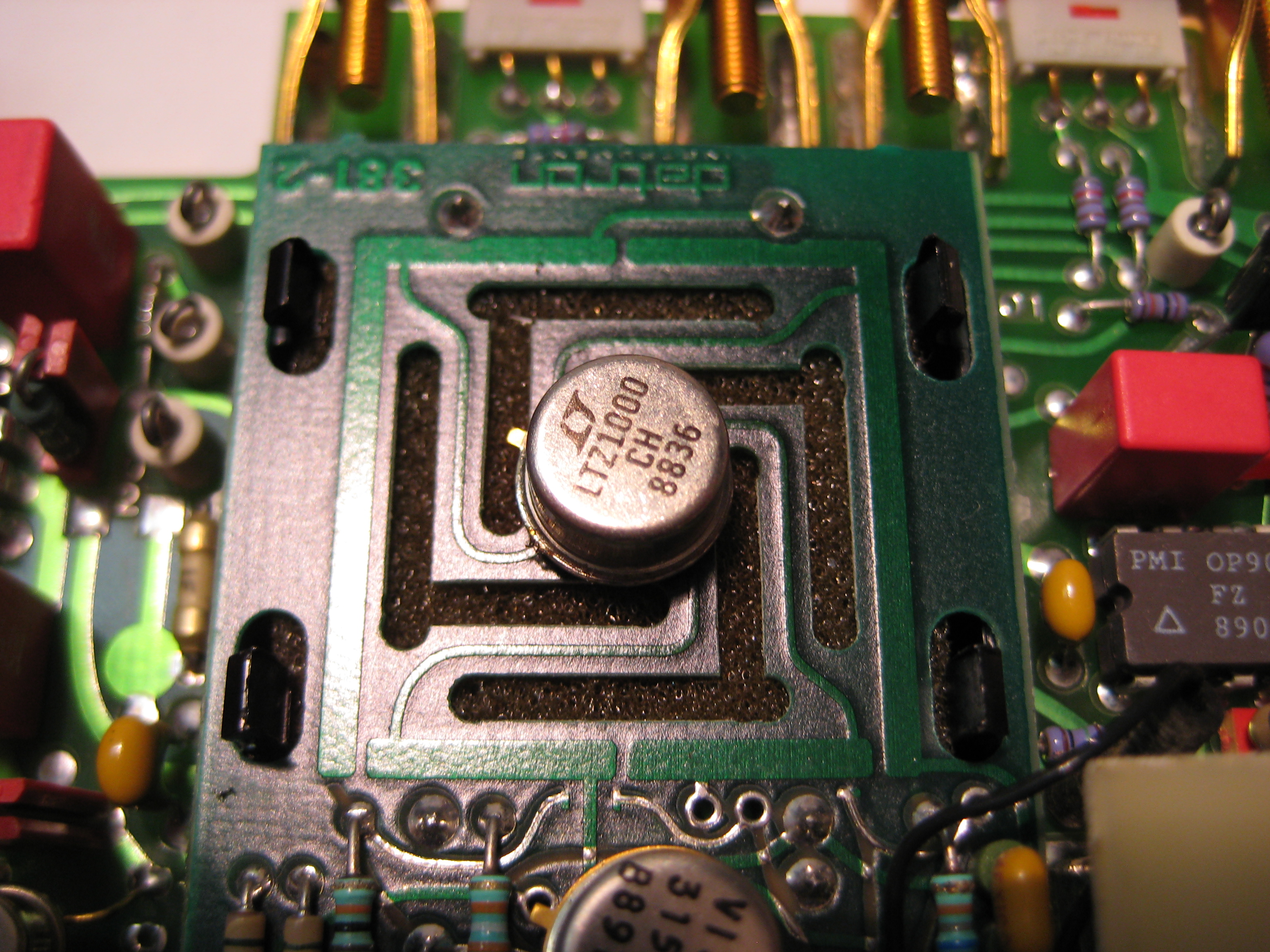
The Datron 4910 seem to be a set of 4 LTZ1000 based 10V references in the same box, the isolation cuts reminds me of something  >:D:


Anyway, we have a flurry of 10V references design, but just one gone calibrator project that died around 2016.


@Kleinstein: The proven track of reliability  has to start somewhere, the digital part is at the level of Arduino/CPLD/ATiny and I will totally not use some obsolete compilers for 6800 ;). Same with the pulse transformers, there are plenty of them to chose from and they cost almost nothing, I don't think that they are something very special to switch a transistorized flip-flop, they have to be balanced and stable, I've seen a some nice candidates.
As I've said, I want to replicate the concept, not the old schematic, on the selection of parts/layout/orientation of tongue ;), after the proof of concept, I'll definitely use the forum wisdom (you're on the first place on the list)  and replace them with their best equivalents in order of influence of the overall quality. A resistive divider it's a divider, it can be made of high precision parts or of affordable parts, as long as we know what it influences, then this is it, the rich will get Vishay vacuum packaged dividers, the poor will put what they have/find, if the general schematic supports it, then it's OK.

 So keep the suggestions, advice coming please, I'll try to answer to everybody, while getting to become friendly with Kicad and do a schematic of the main chopper, hopefully someone will help me with a way to simulate it, especially the Bessel filter.

 Cheers,
 DC1MC
 

Offline Kleinstein

  • Super Contributor
  • ***
  • Posts: 14671
  • Country: de
Only replicating the general concept makes more sense, as the the computer part is old and could be done much easier with newer parts. Just mentioning NOS transistors made me think of a more or less direct copy.

Also for the analog part there are quite a few old style circuits with discrete JFET pairs, which today would likely use JFET OPs. So things might get easier in some areas.

The AC part also has one relatively odd point - the quasi sine generation. This looks odd by todays standards with DDS chips available.
So given modern parts, I would expect a quite different AC section: more like a DDS type generator and possibly also a different kind to AC detector/ amplitude correction.
The AC part might anyway end up as a second, later project.

There are also schematics for the Fluke 57xx around somewhere.  At least worth a look, if you really plan to build such a system.
There are some DIY PWM DAC circuits around too.
 

Online Echo88

  • Frequent Contributor
  • **
  • Posts: 844
  • Country: de
The magic of Datron 4910 lies in its PWM-divider, which substitute the resistor-divider to get 10V.
I have no experience with the Datron-schematics, but thought about the Fluke 5700A-PWM-DAC a lot and might help if questions arise in this respect.
5700A Service Manual with schematics: https://xdevs.com/doc/Fluke/5700a/5700A_old_sm.pdf Page 542 (540-548)
Page 99 presents an overview of the circuit-blocks used in the DAC Assembly.
LTSpice-Simulation of the 5700A-PWM-DAC, including the PWM-Filter you mentioned: https://www.eevblog.com/forum/metrology/2000-post-teardown-and-study-of-fluke-5700a-calibrator/msg1372679/#msg1372679
To get the extremely good specs of such a calibrator you need to understand the circuit-tricks which are used, such as the sense current cancellation or the avoidance of RDSon and its associated losses in switches Q4-7.

I dont want to talk you out of this project by any means.  :popcorn:
 

Offline Johnny10

  • Frequent Contributor
  • **
  • Posts: 900
  • Country: us
I have often wondered if it was possible to replace the reference in a Datron 4000A with the LTZ1000.

You can buy Datrons in US for 400-500 not working.
They use all discrete easy to find parts..
Tektronix TDS7104, DMM4050, HP 3561A, HP 35665, Tek 2465A, HP8903B, DSA602A, Tek 7854, 7834, HP3457A, Tek 575, 576, 577 Curve Tracers, Datron 4000, Datron 4000A, DOS4EVER uTracer, HP5335A, EIP534B 20GHz Frequency Counter, TrueTime Rubidium, Sencore LC102, Tek TG506, TG501, SG503, HP 8568B
 

Offline DC1MCTopic starter

  • Super Contributor
  • ***
  • Posts: 1882
  • Country: de
One more set of answers:

@Echo88 Many thanks for sharing the simulation, I've discovered that, at least for viewing, LTspice works on Linux under wine, hopefully I'll be able to simulate my own schematic. Also thanks for recommending the Fluke schematic, I've only had the most cursory look so far but I'll study it later, now I have a little schematic to finish.

@Johnny10 Don't mention US anymore or I'll start talking about "American privilege"  :-DD, you guys are awash in cool CHEAP stuff, no wonder you lead the innovation in everything, here in the social-democratic world, you have to pay 20% VAT for every derelict crap that you buy for yourself, shipping costs included in the taxable amount  |O. 4-500$ Datron calibrators, it's kind of a dream.

Anyway, the reference voltage question it's a very good one, that I've intended to ask myself to the local volt nutters:

- Could any of those  modern and available 10V references be put in series and still keep a bit of precision and stability ?

- @Kicad friends: does the netlist expored by the strangely named schematic capture program can be loaded into the LTspice, or even better yet, can LT spice be integrated with Kicat (the absolute latest version, nightly).

 Cheers,
 DC1MC
 

Offline DC1MCTopic starter

  • Super Contributor
  • ***
  • Posts: 1882
  • Country: de
Also my eyes are fairly stranded and tired by the crappy quality of the schematics I've found for Datron 4708 and 4707, if somebody has the real deal on paper I'm willing to buy it or pay for a professional scanning to share it with the forum.
Also if there are such quality scans somewhere and I've missed them, kindly please let me know.

 Cheers,
 DC1MC
 

Online Echo88

  • Frequent Contributor
  • **
  • Posts: 844
  • Country: de
Yeah, ebay.de has way less interesting test equipment compared to the US. Can someone please tell again how to see all ebay.com-articles, not only those who are enabled to be internationally shipped?


Offline DC1MCTopic starter

  • Super Contributor
  • ***
  • Posts: 1882
  • Country: de
Yeah, ebay.de has way less interesting test equipment compared to the US. Can someone please tell again how to see all ebay.com-articles, not only those who are enabled to be internationally shipped?
 

This is how I do it, open a private browsing window (Ctrl-Shift-P for Mozilla), go to ebay.com, do NOT login and browse the (almost) unobtainable stuff.
Now if somebody can tell me how to turn off this unbelievable shitty automatic translation on ebay.de, I'll definitely  PayPal you a beer.

 DC1MC
 

Online Echo88

  • Frequent Contributor
  • **
  • Posts: 844
  • Country: de
Nope, there isnt a difference in article-count between Private Mode and normal surfing. I think one needs to use a VPN-tunnel, change the ebay-account to a US-based-adress or something like this.
Want to get a voltage reference like a Datron 4910/Fluke 732A, for a reasonable price.
 

Offline DC1MCTopic starter

  • Super Contributor
  • ***
  • Posts: 1882
  • Country: de
Nope, there isnt a difference in article-count between Private Mode and normal surfing. I think one needs to use a VPN-tunnel, change the ebay-account to a US-based-adress or something like this.
Want to get a voltage reference like a Datron 4910/Fluke 732A, for a reasonable price.

Now and then, using the method described, I got "No international shipping", but more worrisome is the lack of good FETs, booth N and P channels, to replace the J1xx used in the chopper, of course there are a lot of NOS around but it seems that Vishay and everybody else is going to quit making nice FETs :(.

So any suggestion of replacing the following is welcome:
N-FET
Siliconix J112, J108

P-FET
Teledyne J174
Siliconix J175

These were initially sorted according with their parameters, and now only the useless ones are available on the main distributors (I have a feeling that only because were not sold yet, and once gone, they'll be gone 4 ever).

Any suggestions for replacements are most welcome.

 DC1MC


Offline Vtile

  • Super Contributor
  • ***
  • Posts: 1146
  • Country: fi
  • Ingineer
Nope, there isnt a difference in article-count between Private Mode and normal surfing. I think one needs to use a VPN-tunnel, change the ebay-account to a US-based-adress or something like this.
Want to get a voltage reference like a Datron 4910/Fluke 732A, for a reasonable price.

Now and then, using the method described, I got "No international shipping", but more worrisome is the lack of good FETs, booth N and P channels, to replace the J1xx used in the chopper, of course there are a lot of NOS around but it seems that Vishay and everybody else is going to quit making nice FETs :(.

So any suggestion of replacing the following is welcome:
N-FET
Siliconix J112, J108

P-FET
Teledyne J174
Siliconix J175

These were initially sorted according with their parameters, and now only the useless ones are available on the main distributors (I have a feeling that only because were not sold yet, and once gone, they'll be gone 4 ever).

Any suggestions for replacements are most welcome.

 DC1MC
J108 and J112 are still in production from ON semi.
 

Offline jfphp

  • Regular Contributor
  • *
  • Posts: 238
A good starting point for a modern DC V and I calibrator is the Adret/Marconi 103A with its F/V converter. Manual is detailed and the modern circuits allow a tremendous X100 precision and stability (we have allready tried), a dimension downsize... Readout and commands can be made by a PIC or a PC. Another story is the AC.
 

Offline Kleinstein

  • Super Contributor
  • ***
  • Posts: 14671
  • Country: de
Nope, there isnt a difference in article-count between Private Mode and normal surfing. I think one needs to use a VPN-tunnel, change the ebay-account to a US-based-adress or something like this.
Want to get a voltage reference like a Datron 4910/Fluke 732A, for a reasonable price.

Now and then, using the method described, I got "No international shipping", but more worrisome is the lack of good FETs, booth N and P channels, to replace the J1xx used in the chopper, of course there are a lot of NOS around but it seems that Vishay and everybody else is going to quit making nice FETs :(.

So any suggestion of replacing the following is welcome:
N-FET
Siliconix J112, J108

P-FET
Teledyne J174
Siliconix J175

These were initially sorted according with their parameters, and now only the useless ones are available on the main distributors (I have a feeling that only because were not sold yet, and once gone, they'll be gone 4 ever).

Any suggestions for replacements are most welcome.

 DC1MC

Many those fets are still available in SMD (SOT23) case as MMBFJ...,
MMBFJ112 and MMBFJ175 are no problem to get.

If I understand the Datron design correct, it uses very low ohms and matched switches. The Fluke5700 design uses compensation of the resistance by using separate switches to supply most of the current.
 

Offline DC1MCTopic starter

  • Super Contributor
  • ***
  • Posts: 1882
  • Country: de

Now and then, using the method described, I got "No international shipping", but more worrisome is the lack of good FETs, booth N and P channels, to replace the J1xx used in the chopper, of course there are a lot of NOS around but it seems that Vishay and everybody else is going to quit making nice FETs :(.

So any suggestion of replacing the following is welcome:
N-FET
Siliconix J112, J108

P-FET
Teledyne J174
Siliconix J175

These were initially sorted according with their parameters, and now only the useless ones are available on the main distributors (I have a feeling that only because were not sold yet, and once gone, they'll be gone 4 ever).

Any suggestions for replacements are most welcome.

 DC1MC

Many those fets are still available in SMD (SOT23) case as MMBFJ...,
MMBFJ112 and MMBFJ175 are no problem to get.

If I understand the Datron design correct, it uses very low ohms and matched switches. The Fluke5700 design uses compensation of the resistance by using separate switches to supply most of the current.

Your understanding is, of course, correct, the J108 it's the elephant in the room, and I've seen the MMBFJ guy but seem to be off regarding the specs of the originals.

 Well, we'll see what comes of it, most of the stuff it's ordered, the scary part it's the filter but for a proof of concept I should use what it's around.

 Many thanks for the support, advice from masters like you are always most welcome .

 Cheers,
 DC1MC
 

Offline Kleinstein

  • Super Contributor
  • ***
  • Posts: 14671
  • Country: de
The filter part should not be that scary. I don't know the circuit of the 4708, but the 4910 filter looks not that bad, if one uses modern JFET based OP instead of the old  discrete JFET pair + NE5534.

For the MMBFJ... types and the exact specs, I have seen datasheets which are for both J... and MMBFJ... with the only difference in the case. There can be some differences depending on the manufacturer. Also the ultimate leakage and maybe low frequency noise may be effected by the case, but hardly low impedance digital switching parameters. There is quite some scattering in the parameters anyway. So a J109 might well meet the J108 specs if one is lucky.  As they seem to use some compensation, it might need selected fets.
 

Offline MK

  • Regular Contributor
  • *
  • Posts: 237
  • Country: gb
A good starting point for a modern DC V and I calibrator is the Adret/Marconi 103A with its F/V converter. Manual is detailed and the modern circuits allow a tremendous X100 precision and stability (we have allready tried), a dimension downsize... Readout and commands can be made by a PIC or a PC. Another story is the AC.
A quick google did not turn up any, do you have a location to share where one could get the manual(s)?


Online Echo88

  • Frequent Contributor
  • **
  • Posts: 844
  • Country: de
 

Offline Kleinstein

  • Super Contributor
  • ***
  • Posts: 14671
  • Country: de
The instructions have an English part at the end.

The Adret 103A is using a similar PWM ADC type to the Fluke5700 or Datron 4910,...
However it looks like lower quality, with an LM399 reference and using just CMOS logic chips to drive the PWM. The OPs also look a lot less accurate.

I would consider using CMOS switch ICs like DG419 and the on resistance compensation like the Fluke circuit. This would be considerable easier than the discrete FET switches and could also have less transient load on the reference sources. Those low resistance switches from discrete FETs can have quite some transients seen by the reference - so one would need quite some filtering here.
AFAIR the resistance compensation scheme needs a voltage that is something like 50% higher for the compensation. So with a maximum of some 30 V for the DG419 one could in theory go up to about 20 V reference if really wanted. I would still expect the reference buffer before the PWM stage one of the more tricky parts. Chances are one could use something like a 14 V reference as a starting point, from two 7 V reference in series or for the beginning with a times 2 amplifier.

The fluke circuit includes an optional a times 2 gain. This makes the circuit look rather complicated. It gets much simpler without that extra optional gain.
 
The following users thanked this post: DC1MC

Offline DC1MCTopic starter

  • Super Contributor
  • ***
  • Posts: 1882
  • Country: de
@Kleinstein Well, if you can sketch something that replaces those bloody sorted and "endangered species" JFETs with some COTS circuits, it will be sehr nett :). Any picture of a piece of paper will be enough, it can't be worse than the Datron 4708 schematics that I have.
My goal is to produce a reference divider as a module, that depending of the quality of used components could go as precise as possible. The Datron one seem to be the one that I understand the most and seem doable within my means, that mean a bit over average volt passionate, so to say ;).
Looking at Fluke's diarrhea of relays and complications I've been kind of put off, but if you can somehow simplify it and still keep it precise and doable, then it's wonderful.
At my level
I was just looking at some Ethernet network and ISDN pulse transformers, they are dirt cheap, because another goal is to keep it reasonable cost effective and with parts with a long active life, no some soon to be unobtaniums. I've replaced so many optos that I've kind becoming allergic to them ::).

Anyway, if nothing will show up, I'll continue with the Datron calibrator implementation, but it's never too late for a good design.

 Cheers,
 DC1MC
 

Offline Kleinstein

  • Super Contributor
  • ***
  • Posts: 14671
  • Country: de
In a simplified version the R_on correction and thus linearity improvement Fluke is using in the 5700 is about in the way shown in the attached drawing. I hope I got the resistor rations right. The circuit is wrong with the lower 2 OPs ! The main idea is that essentially all the current is coming from the lower PWM switch with the higher voltage and the upper switch is only correcting small errors. This way the current through the upper switch is very small and thus the on resistance much less important.  In the form shown the lower switch has a differential voltage that is 1.5 times higher than the original reference.

The filter in only simplified with a simple switch. The main buffer should likely be an AZ type, possibly with an extra driver and sense. It might also need an extra buffer for the dividers - but this depends on the rest of the circuit.

With modern µCs I would not use galvanic insulation for the PWM signal, but get the PWM signal directly from an µC (e.g. AVR or similar 8 Bit) and only send control values via UART and opto-coupler. The modern µCs tend to cause not much more noise / spikes than  sychronising flip-flops needed if the PWM signal is send via pulse transformer or similar.

p.s. corrected version of the circuit is at post #32/33
« Last Edit: November 18, 2018, 09:02:41 am by Kleinstein »
 
The following users thanked this post: DC1MC

Offline branadic

  • Super Contributor
  • ***
  • Posts: 2435
  • Country: de
  • Sounds like noise
It's been a while ago now that I've worked on the schematic for a PWM-DAC based on the approach presented on EDN and modified by Andreas. Still haven't managed to draw the board, but will go on soon. I put the schematic here for your inspiration.

-branadic-
Computers exist to solve problems that we wouldn't have without them. AI exists to answer questions, we wouldn't ask without it.
 
The following users thanked this post: DC1MC

Offline Kleinstein

  • Super Contributor
  • ***
  • Posts: 14671
  • Country: de
If I remember right the EDN circuit was not that linear. There is no compensation for the switch resistor difference, and the max4053 switch is relatively high resistance.
The interesting part might be the filter: it is a sampling filter, that could thus result in very good ripple suppression. However sampling a signal with some ripple (after a first and maybe second filter stage) will cause some error and thus nonlinearity unless there is a phase adjustment to sample at zero crossing).  For use with a DMM, i would prefer ripple over nonlinearity.

I just found an old thread about PWM DAC. It looks like someone already kind of copied the datran 4910 circuit.
https://www.eevblog.com/forum/metrology/volt-reference-diyer-ltz-10v-pwm/msg1246656/#msg1246656

The copy is quite close to the original - one could definitely replace the JFETs + NE5534.
 
The following users thanked this post: DC1MC


Share me

Digg  Facebook  SlashDot  Delicious  Technorati  Twitter  Google  Yahoo
Smf