I will certainly contemplate putting a cap between the two rails right on top of the chopper amp, but for the moment, I'm looking at the PLL and oscillator board.
I had performed the very simple check from the manual (measure voltage at test point, if it's 3V +/- 0.2V you're good) but hadn't looked at the inputs to the PLL chip to see if they were actually locked. So last night I got the Rigol on the test points and discovered this:
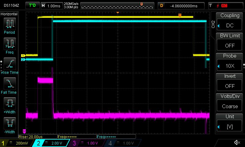
(ch1 is MAINS_IN, ch2 is COMP_IN and ch3 is the clock control)
It's not exactly what you'd call locked and regardless of the control signal trying to pull the COMP_IN signal back into phase with the mains, the phase difference was fairly constant, which is more than I can say for the frequency with never settled on anything.
So I twiddled the adjustment on the clock board until the PLL managed to lock the two signals, but the result was less than great. It would correct the phase, but the response was horribly slow. If the COMP_IN signal drifted before the MAINS_IN signal, it would produce a negative signal on the clock control to push it back. If it drifted after, it would produce a positive signal to pull it back again. If the phases were locked, the clock control would remain at the mid point. Sounds good, and that's what it's supposed to do, except I'd expect it to take
much less than several seconds to re-lock the phases and I'd also expect the lock to stay locked after maybe a minute at most, but no. It would drift forward and backwards all the time and the clock frequency would never stabilise.
So I've now taken the clock board out of the meter and have it running on the bench with the clock control input fixed at 3V. After a few minutes to warm up and stabilise, it's holding stable. Except the frequency is 52.346 MHz instead of 49.152 MHz. So I'll adjust it to 49.152 MHz, put it back in the meter and see if the PLL can now manage to phase lock the clock to the mains frequency and keep it there. If not, I guess it's time to start tracking down an MV2115 varactor diode.
I looked at the circuit diagram of the 49.152 MHz crystal clock option and was very surprised to find no input for the PLL control signal. A crystal is going to give a more stable frequency, but surely it still needs to be phase locked to the mains for proper AC interference rejection?


