'Test 1.
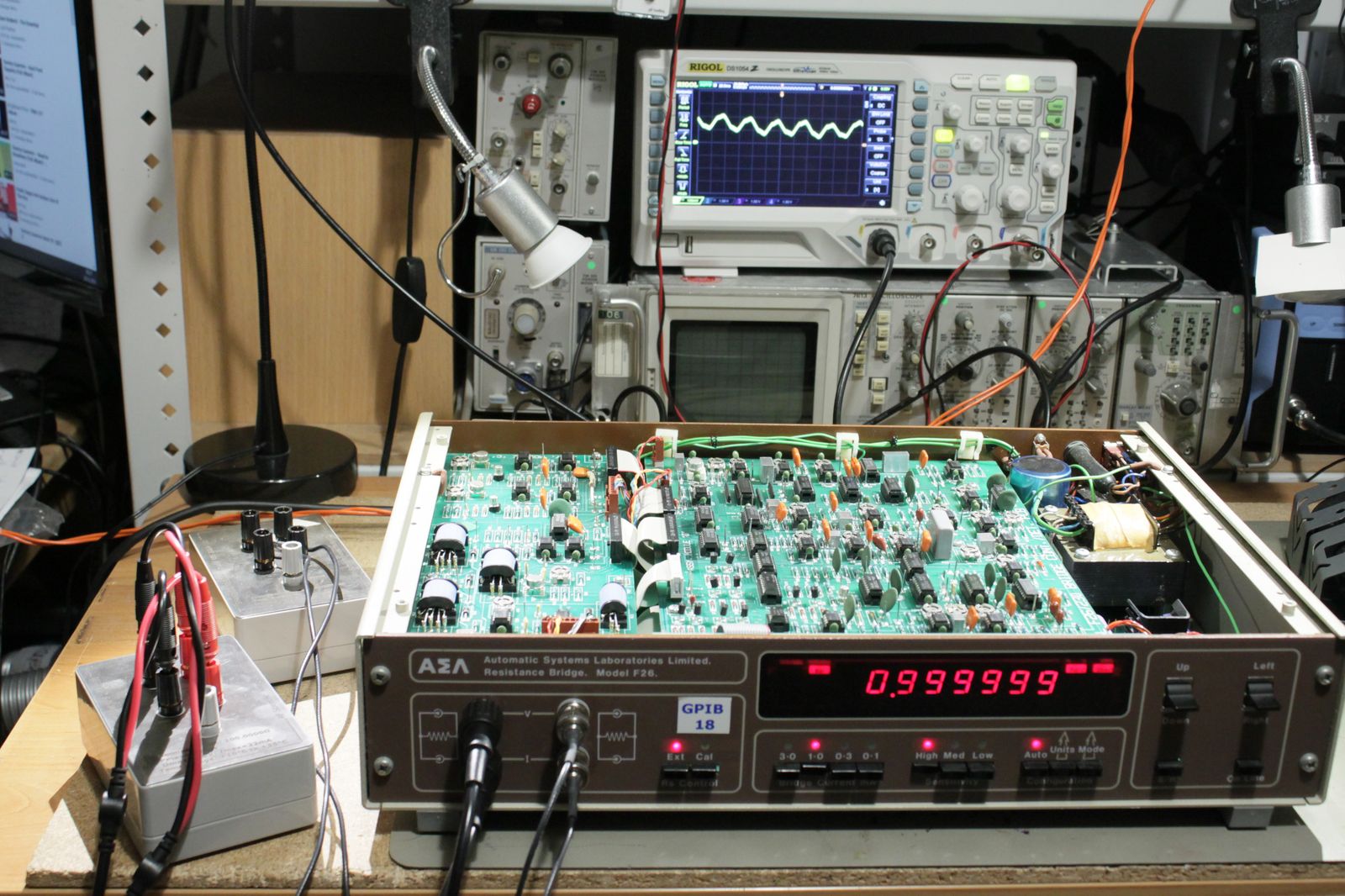
Two 100Ohm resistors connected as RS and RT as fig.1.1.1 Set current to 1mA; ext RS; sensitivity (detector gain) high; ratio mode; cal off.
Does the bridge balance in auto? Try again in low and med gain – auto balance should slow down.
You should also see 100mV RMS on RS and inverted on RT (input and output of active guard circuit (see fig. 1.2.1, basically an inverter). Do not connect scope 0V to virtual earth – use the earth terminal on rear panel.'100mV RMS +/-1% at 100R. Other current ranges also correct within 1%.
Result: OK. See photo below.
25Hz ripple visible on the scope.
 'Test 2
In manual mode set the ratio to 1.00000; low gain and observe detector output (BNC rear panel). Vary the manual ratio setting up and down (top 3 decades from 0.00 to 3.99). The detector DC output should be proportional with no obvious gaps.
Note: On max gain you should get approx ±1V for ±1 digit in the 5th decimal place (±0.00001) and pro-rata for med and low gain settings. Similarly for different current settings: more current = more DC change per digit.
If there are jumps suspect a dry joint or one of the relays (transformer tap selection) not working.'Result: OK. No gaps.
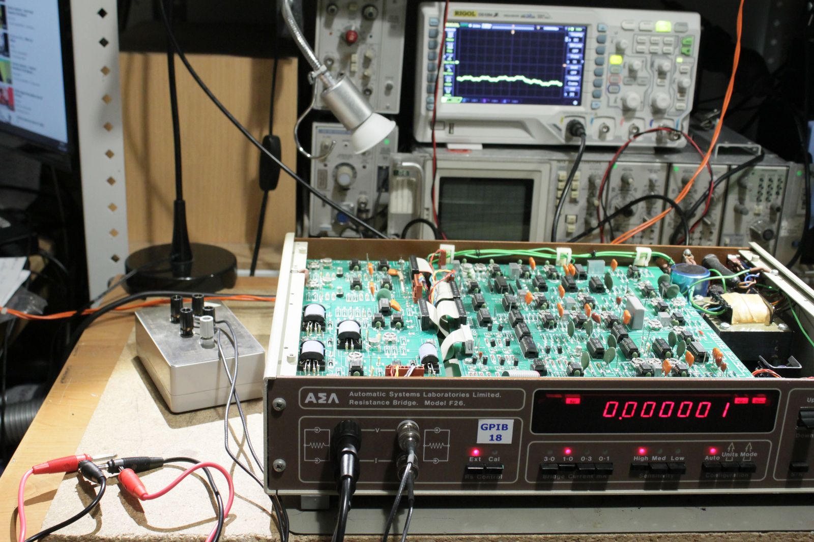
'Test 3
The last three digits is implemented with a multiplying DAC and added in series with the main xformer output.
Connect both RT volt sensing leads to same point on RT (virtual earth side) equivalent to a RT=0.
Manually set ratio to zero and check for balance. Increase one digit at a time on max gain. The DC output should change accordingly, with no gaps.'Result: OK. No gaps. It was not mentioned, but if I start to adjust 6th decimal place there is some weird behavior. from 0 to 4 nothing changes, then from 5 to 14 is some constant value.
I suspect this 6th decimal place can be obtained from residual voltage measurement (?).
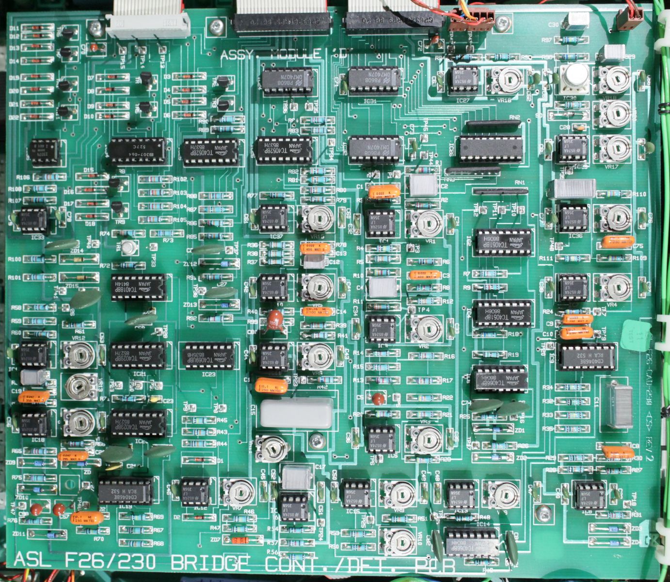
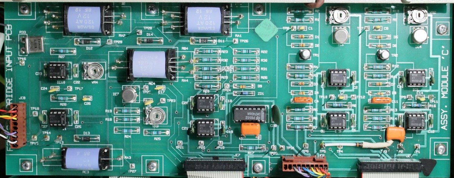
Below two more detailed photos of the analog part. The size is limited to 500KB on my website.
P.S. power supplies seem to be working correctly with reasonable voltages and relatively low ripple.


