Gee, I spammed for long enough to reach post
#3000!

Time to spend less time at the keyboard and use soldering iron more often!

So what would be a worthy read? Another LTZ reference? I think everybody already tired of all of these, spawning like mushrooms during 2017. Ongoing battle of BMF resistors vs PWWs? Nah, they all are good beans. Keithley gear teardown? I think we saw it all already here or there. But there is one instrument that was not discussed much on EEVblog!
 Intro
IntroWelcome almighty Fluke 5790A! One sad day (for instrument ofc, not for me) I got a call from my Taiwanese friend, seeking for assistance with 5790A that went belly up.

The
Fluke 5790A AC Measurement Standard today is already replaced by
face-lift version Fluke 5790B. both of which are share same chassis and architecture. 5790B essentially same thing, but with fancy
ugly LCD instead of warm fuzzy VFD, and support easy A40B shunt operation for ACI measurements and 50MHz wideband option, useful for power sensors calibration.
5790A can perform direct measurements of unknown signals or perform relative transfers between known and unknown input signal. In measurement mode, the Fluke 5790A operates as a digital accurate AC voltmeter with up to 8 digits of resolution. Measurement mode uses an internal stable DC reference to compare with unknown AC input.
In transfer mode, external DC or AC reference source can be supplied to unit to perform a comparison. The 5790A automatically performs switching and calculations, and displays the resulting AC-DC or AC-AC difference. The 5790A has multiple input voltage ranges, with acceptable signal levels from 700 µV to 1000 V (70 mV minimum in transfer mode), and a frequency range of 10 Hz to 1 MHz. A wideband option allow frequency range extension to 30 MHz, however unit we study today have base configuration without WB option. The 5790A is also compatible with Fluke A40 current shunts, which allow to make AC-DC or AC-AC current transfer measurements up to 20 Amp.
InspectionSo meter failed after one of such measurements, reporting now alarmingly blinking
HHHHHHHH overload message on any range with no signal applied to it.
No goodski. Perhaps input fuse or MOV blew up, you say?

Oh wait, it's
Metrology section here, we don't escape blowing up 60000$ instrument that easily.
For a better picture, it was the very same meter that I used as reference in my own calibration of Wavetek 4920M back in November 2016. Now good old 4920M outlived its modern brother.

Which is no surprise as my 4920M mostly chilling at the desk, and 5790A was used to calibrate high-power AC sources.
The 5790A AC Measurement Standard is designed as complete device to perform automated AC-DC transfers and for use as laboratory standard. All measurements are automated by internal microprocessors, so use of the AC measurement standard is simple as typical DVM. However unlike more general purpose DVM and DMMs, Fluke 5790 purposed to do Alternating voltage (AC) measurements. The following elements are among those critical to establishing the high accuracy of the 5790A. Core of the performance is custom Fluke designed thermal sensor hybrid.
- The FTS is the transfer element. It compares a precisely known internally generated DC voltage (or a low frequency square wave derived from DC) to an unknown AC voltage. If the FTS output remains unchanged when the input switches from the unknown AC voltage to the known DC voltage, the RMS value of the AC voltage is equal to the DC voltage. The FTS has extremely flat frequency response and has short term stability approaching 1 ppm.
- Highly stable thin-film resistor networks scale the 7 V range and higher to the FTS 2 V operating level and to scale the precision chopped reference to the 0.7 mV level.
- An ADC to measures the FTS output voltage and compare with known DC level.
- A high-resolution very linear DAC (digital to analog converter) generates precisely variable DC for the AC-DC transfer.
- An ultra-stable DC voltage reference based on two Linear/Fluke LTFLU-1ACH ovenized reference module establishes long-term DAC accuracy and low noise.
- A DC-to-square-wave converter chops the DAC output to eliminate DC reversal error in the RMS sensor.
Front panel and chassis repeat design of Fluke’s 57xx-series multifunction calibrators, such as 5700A.
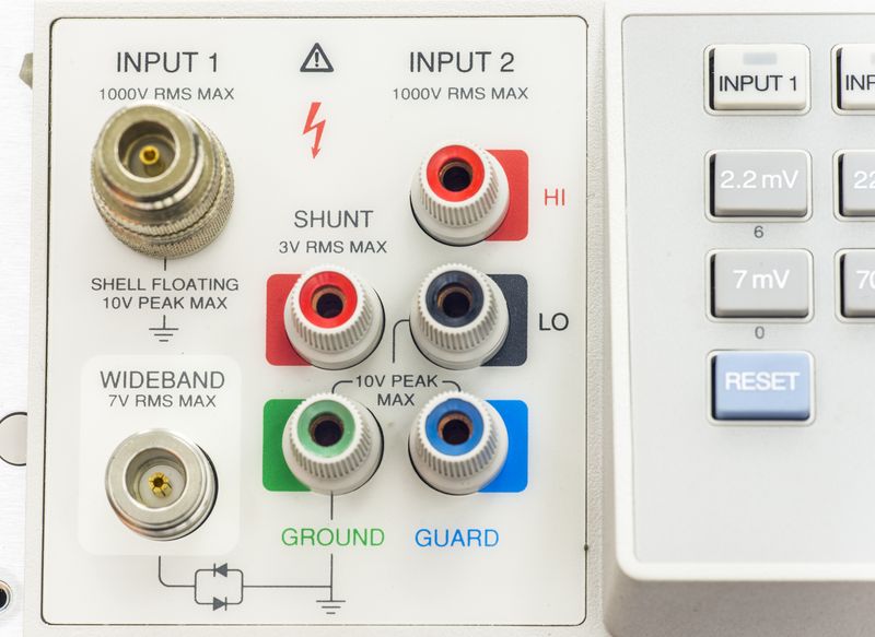
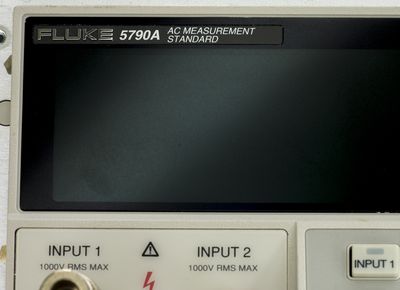
A variety of input connections allows versatile use that best suits specific application and equipment interfaces. There are four sets of input terminals on the 5790A, two 50? Type “N” connectors and two sets of five-way binding posts. One 50? Type “N” and one set of binding posts is dedicated to the AC measurement and transfer modes.
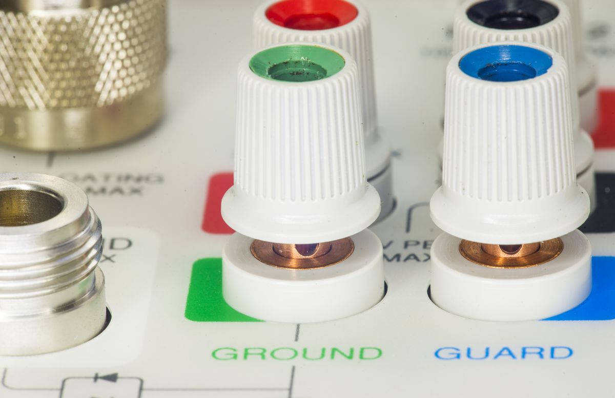
Unlike some older standards like Wavetek 4920M, AC or DC voltages can be applied to either input connection, allowing you to perform automated AC-DC transfer measurements. But binding posts are the only ones recommended for DC, due to parasitic thermal EMFs of N-connector.
The second Type “N” input connection supports only the optional wideband mode, and is unconnected internally on standard 5790A. SHUNT binding posts are for Fluke A40 Series current shunt connection.
So after initial verify, I've powered on the box, and ran self-diagnostics to see what we get.
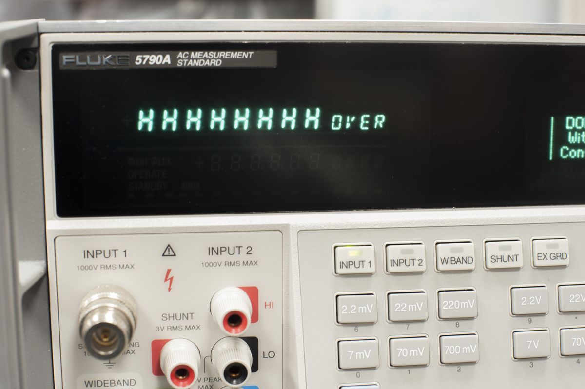
Well, it got nearly all possible errors popping like crazy...
FAULT? = 103,"Cal/Diag not Halted"
FAULT? = 409,"A10 Transfer: Dormant Protection Check"
FAULT? = 413,"A10 Transfer: LO V Input Path"
FAULT? = 413,"A10 Transfer: 220V Input Path"
FAULT? = 413,"A10 Transfer: 22V Input Path"
FAULT? = 410,"A10 Transfer: Overload Check"
FAULT? = 412,"A10 Transfer: 7 mV Range Zero"
FAULT? = 412,"A10 Transfer: 22 mV Range Zero"
FAULT? = 408,"A10 Transfer: 2.2V Range"
FAULT? = 408,"A10 Transfer: 7V Range"
FAULT? = 408,"A10 Transfer: 7V Range"
FAULT? = 408,"A10 Transfer: 22V Range"
FAULT? = 408,"A10 Transfer: 22V Range"
FAULT? = 408,"A10 Transfer: 70V Range"
FAULT? = 408,"A10 Transfer: 220V Range"
FAULT? = 1,"Error Queue Overflow"

After removing external top metal shield we can see separate shielded sections for inguard precision circuitry and outguard section on the right with mains custom transformer and digital processor board and power supply assembly. Also there two 92mm size cooling fans.
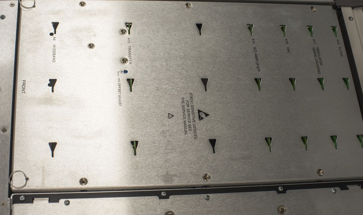
Chassis is very same as 5700A/5720A, so I'm already familiar with design concept here. Opposite to 5700/5720A inguard section have a lot of free space. and essentially have only 5 boards (6 with Wideband PCBA). We will take a look on each of the boards in better detail in next section. Essentially it looks like stripped 5700A as there are no boards that handle all various signal generation, needed for 5700-calibrators.
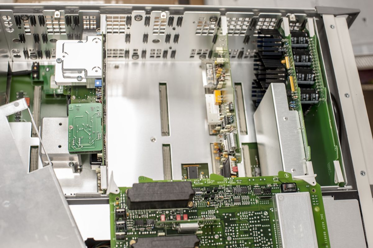
Just 5 boards inside inguard section, that's it. Wideband option would be board in front of A10.

As I had chance to peek inside 5790A now, I carefully took photos of all PCBs, except backplane ones for our enjoyment and history preserve.
A16 PCBA – DAC + main DC Reference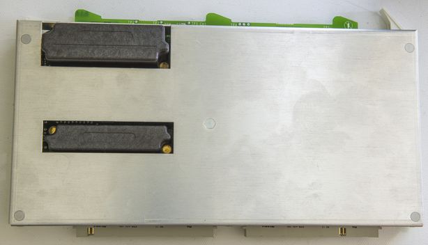
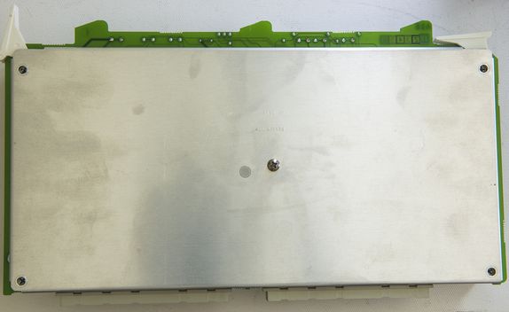
“Magical” reference, based on two Linear LTFLU ref-amps. Design of this high-performance non-heated buried zener was covered in better detail in 5700A thread. It's essentially very same DAC board used in calibrators, but with removed null-meter ADC section.
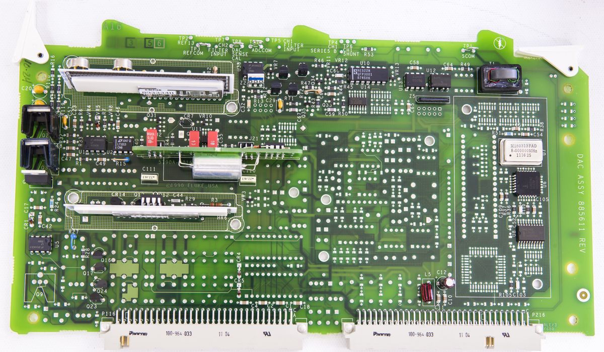
Here's volt-nut $$$$-shot you all were looking for:
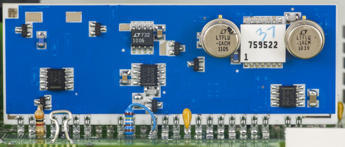
Dual LTFLU-1ACH with Fluke Hybrid resistor network 759522, placed on alumina substrate, heated to +62C for best stability. Interesting to note that left LTFLU made in 5th week 2011, while right one is 39 week 2010. Perhaps cherry-picked by nude virgins for best noise/drift rate?
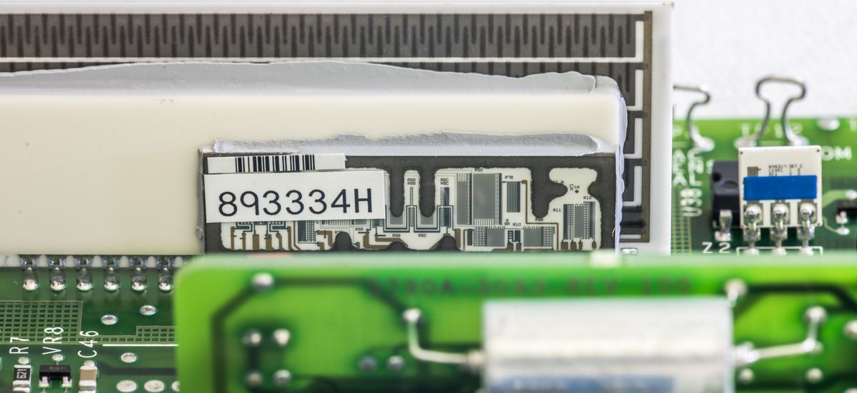
Additional precision resistor network P/N 893334H is thermally bonded to the back of the ceramic assembly. Whole module is covered by plastic cover to avoid air drafts and maintain constant air bath temperature inside.
Many parts missing on board

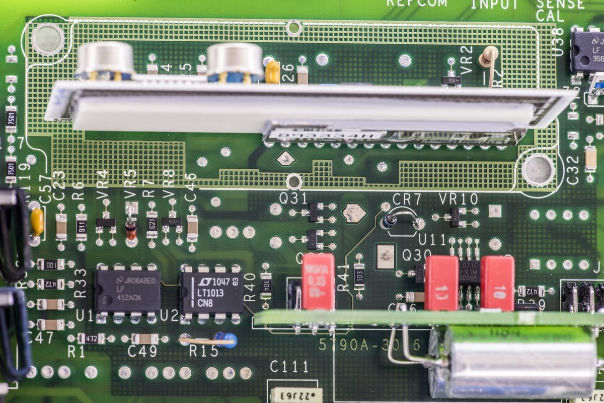
Heated chopper output buffer for reference is still there, populated.
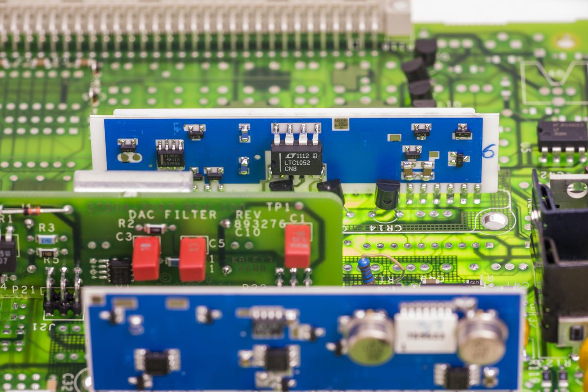
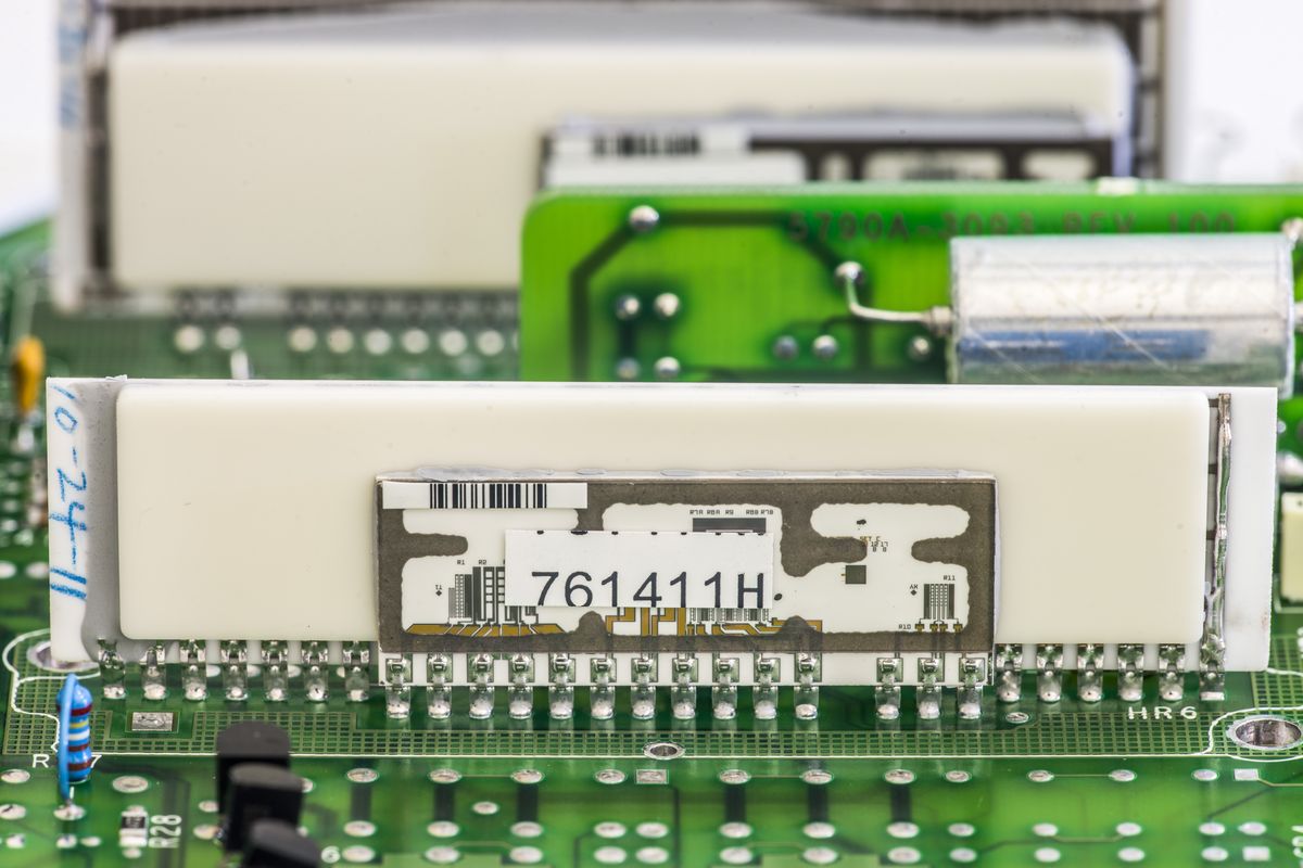
While I was looking on the board, I noticed something:
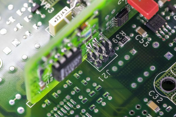
WTF? Solder blob at connector J21!. I didn't even get iron hot, and there are already solder blobs inside?

Removed this carefully, but that was not the reason why unit failed anyway.
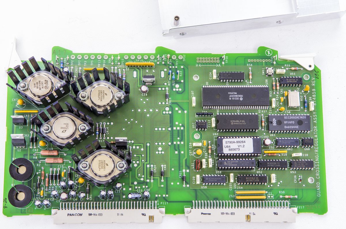
A17 PCBA – Inguard crossing and regulated supply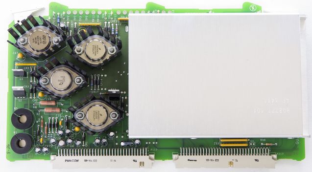
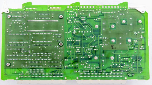
This board is also nearly same as one from 5700A.
 A18 PCBA - Unregulated power supplies
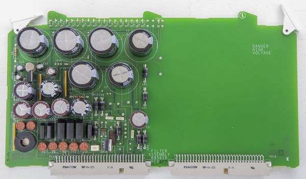
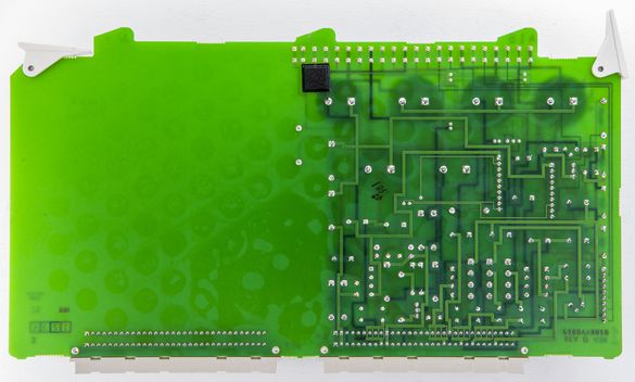
Semi-empty assembly with regulators and filter caps. There is no need for high voltages in 5790A, so related supply part is completely missing.
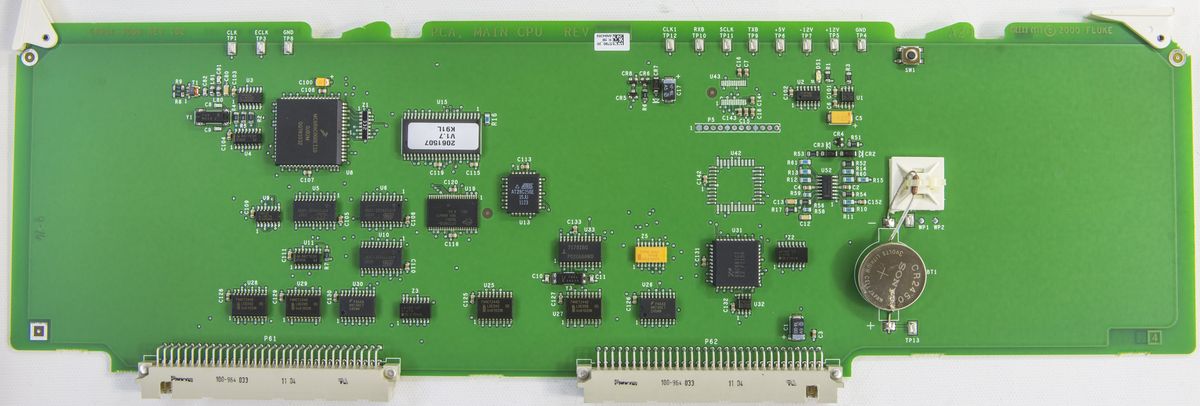
A20 PCBA - Fluke 5790A main processorThis module contains all the digital "brains" of the instrument. It's newer SMT version. Same board used in modern 5720A's.
 A19 PCBA - Outguard power supply
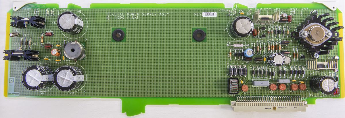
Same board as 5700. Middle empty space is provision for custom Fluke mains transformer.
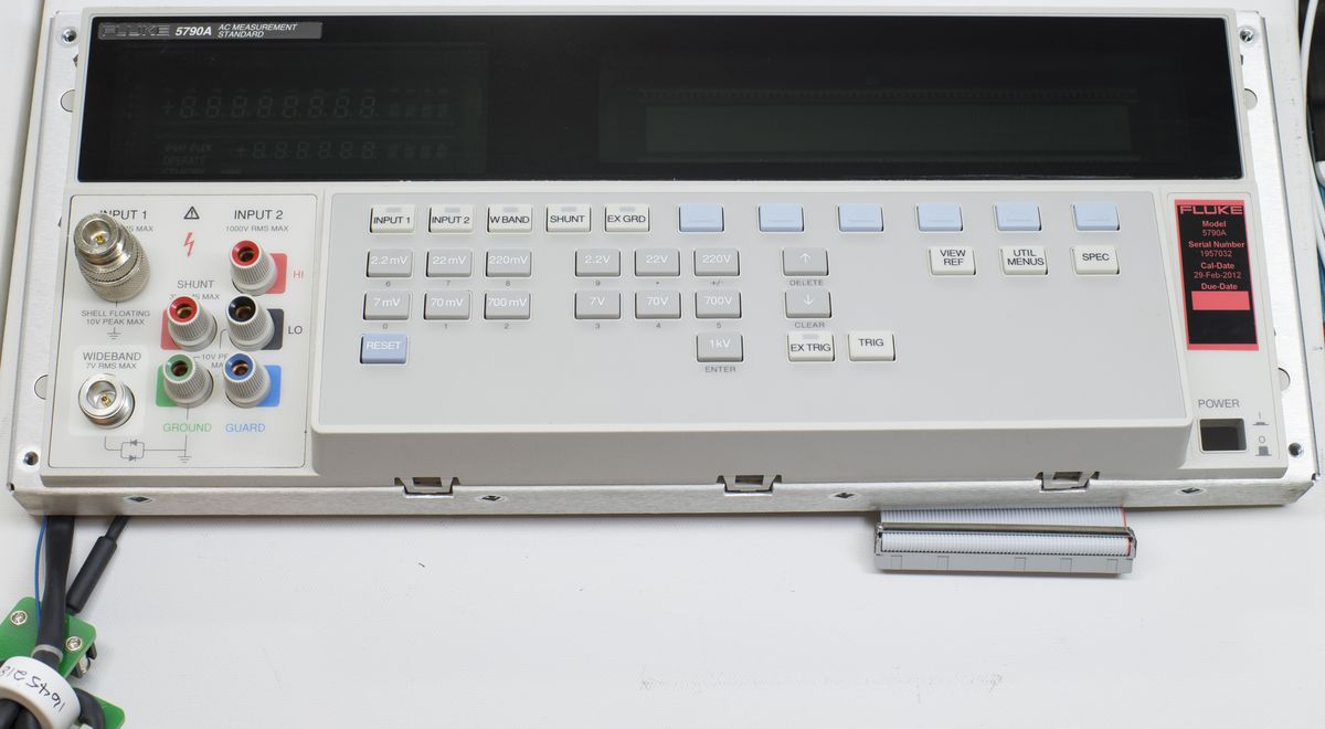
Front panel assemblyFront panel is very same to 57xx. VFD glass is exact.
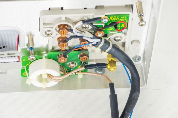
Connector assembly for front panel had own little cute boards.
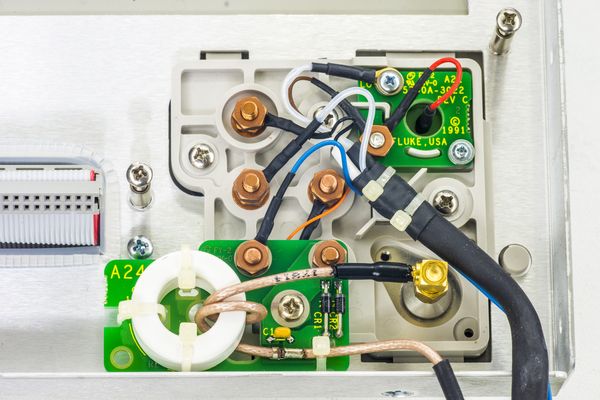 Repair
After checking all main inguard and outguard power supply voltages (all were good, as expected), it's time to look at the sensor for investigation.

Fluke 5790A RMS sensor contain Beryllium Oxide ceramics. While normal use of 5790A is safe, BeO dust or fumes from damage to these component are HIGHLY TOXIC and breathing them can result in serious injury or worse.
The sensor chip itself consists of two closely matched thermal voltage converters that use the temperature sensitivity of the transistor base-emitter junction in the place of the traditional thermocouple. External to the sensor chip is an error amplifier that is used to drive the second or feedback resistor/transistor pair. The output of the circuit is a dc voltage linearly proportional to the rms value of the input signal. Design requirements necessitated several modifications to the sensor and essentially pushed the sensor design to obtain the low noise, wide dynamic range, and fast settling time needed.
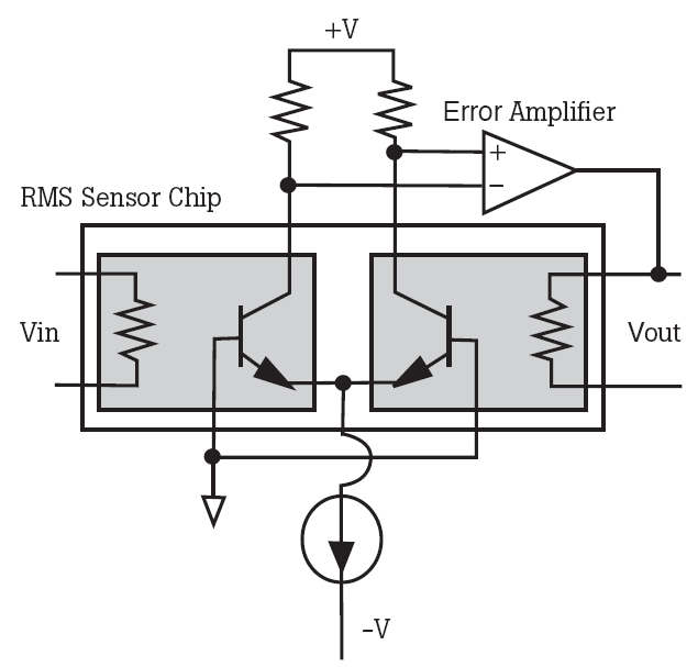 Fluke Thermal RMS sensor. Courtesy Fluke 792A Application note
I already knew that same sensor also used in
5700A-series calibrators and which we saw in
Todd's article about Fluke 792A transfer standard box. The FTS consists of two identical islands suspended in air, each containing a heater resistor and an NPN transistor. Each island provides close thermal coupling between the resistor and transistor. Between islands, there is high thermal isolation. As shown in the schematic, these two transistors are connected as a differential gain stage with a differential input voltage of zero volts. Applying a voltage to the resistor on one of the islands causes that island to heat up. Good theory in detail explain in service manual.
And this thermal sensor is now dead, as it's input resistor is >1GΩ, essentially open. Normal resistance range for Fluke Thermal Sensor is 400 Ω.
As unwanted bonus, we now take dead sensor apart to have a quick peek of it's internal design.
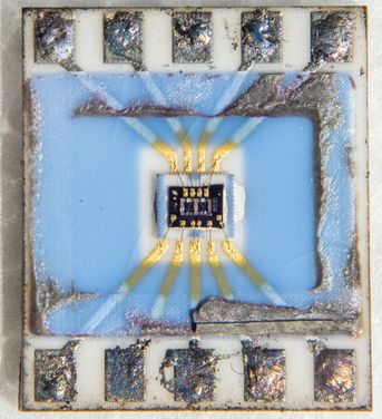
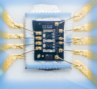
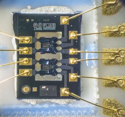
The chip itself have original Fluke logo and have design year date 1986. Sensor chip build with three design features:
* Silicon die with input and isolated output sections.
* Small alumina interposer carrier for silicon die to decouple mechanical stress.
* Main alumina substrate with metallized traces
An over-voltage protection circuit monitors the base-emitter voltage of the sensor transistors. As with other silicon junctions, the base-emitter junction on the FTS transistors exhibits a -2 mV/°C temperature coefficient. When the base-emitter junction falls below 200 mV, the output of U4 goes from -15 V to +15 V, turning on Q1. This shorts the sensor input to ground through the diode bridge, CR7 through CR10 and allows the FTS to cool. When the temperature falls and the base-emitter voltage increases past the 200 mV threshold, U4 again changes the state and turns off the clamp.
During a continuous overload, the protection circuit oscillates between these two states. To facilitate rapid auto ranging, the output of U4 generates an interrupt signal for the CPU by turning on Q6. This way the CPU can react quickly to an overload at the FTS.
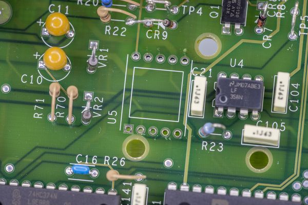
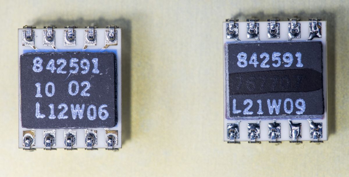
So after few months of hunting, I managed to buy working Fluke 5700A A12 board, which have two of desired sensors... TRMS sensor from donor 5700A board on the left, original 5790A A10 TRMS sensor on the right.
Direct input to TRMS with K7 removed for testing:
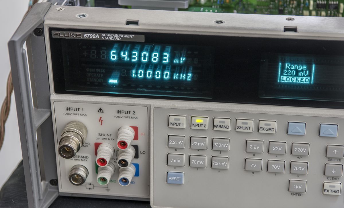
That did not bring a salvation thought, as after running few self-diagnostic tests replaced sensor blew up too! About a month worth of digging and measurements with dummy transistors instead of real sensor hinted why that happened. Overrange circuit operation was modified to reduce maximum signal level to trigger the protection mechanism. After checking lower levels, I've replaced once again, using second A12 chip, and now unit worked as expected.
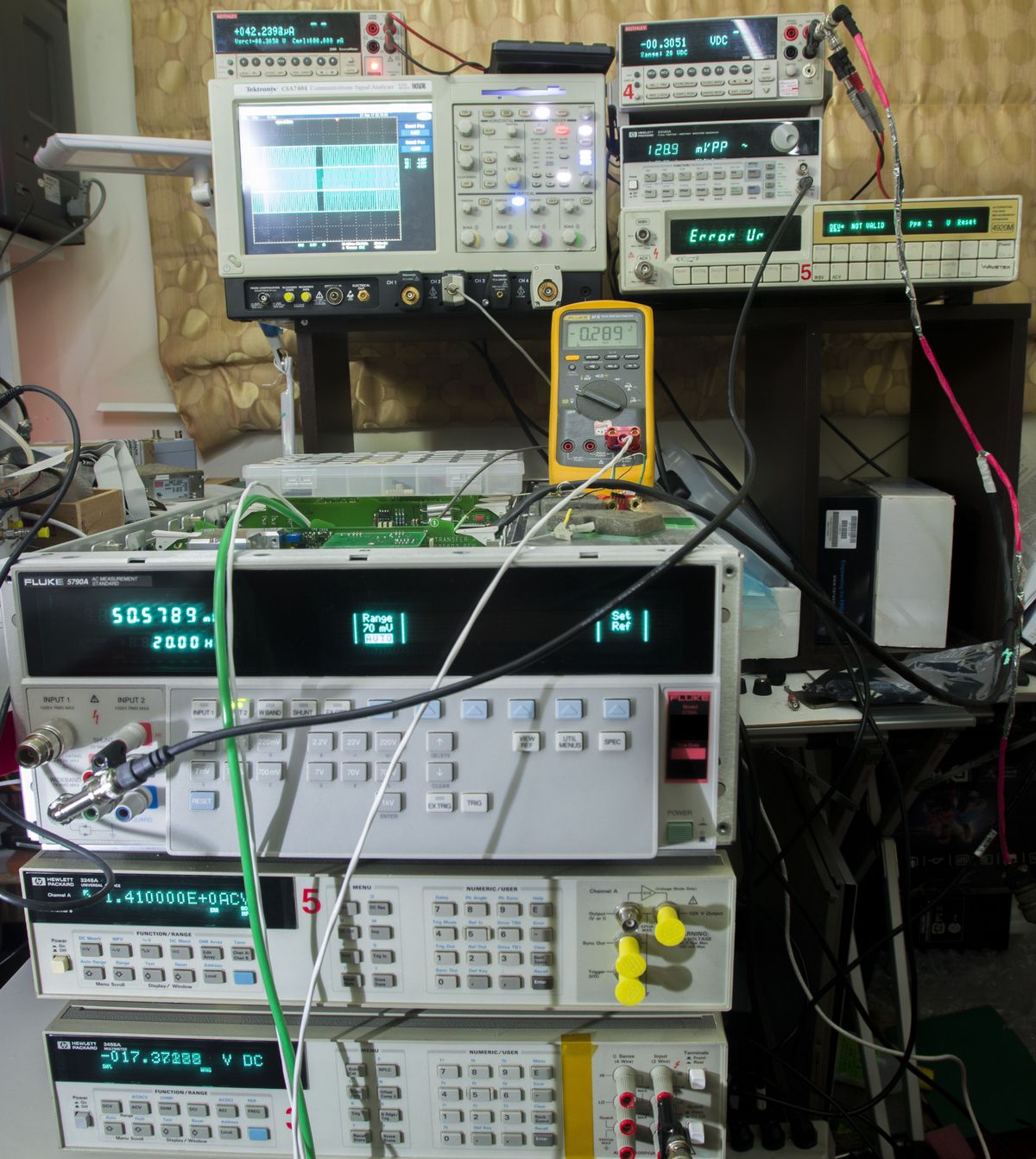 Testing stability and comparison to other meters
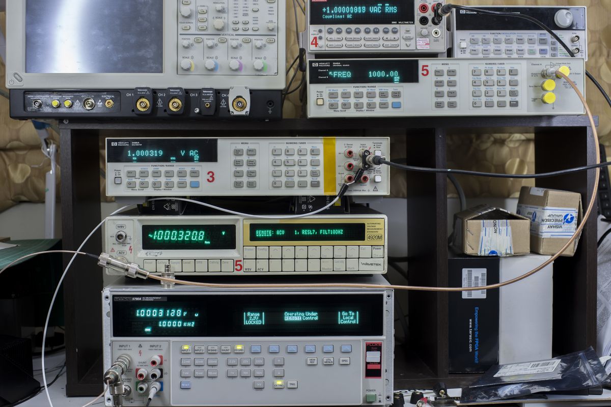
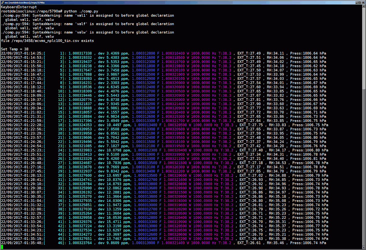
Also as part of verification I compared 5790A versus Wavetek 4920M and our usual go-to meter, HP 3458A. All graphs clickable for actual data/SVG.
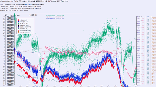
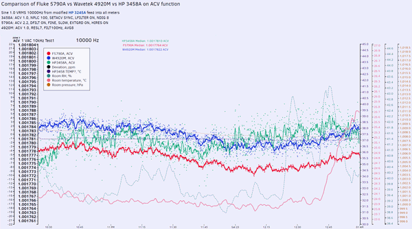
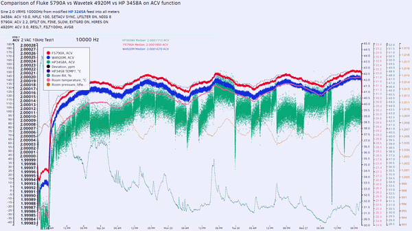
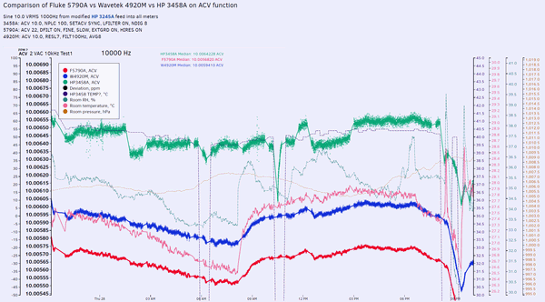
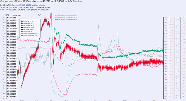
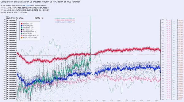
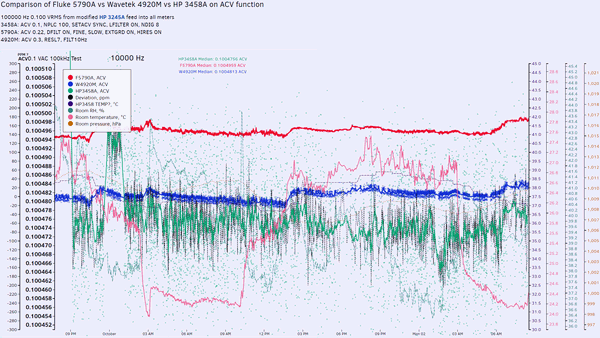
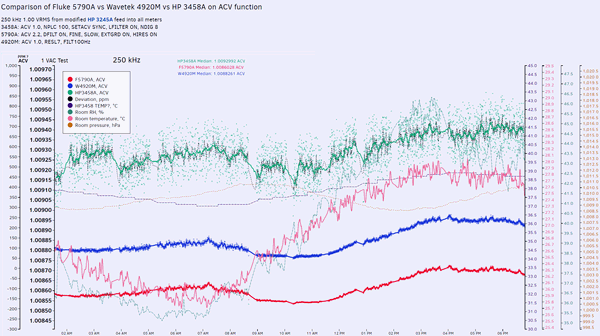
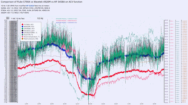
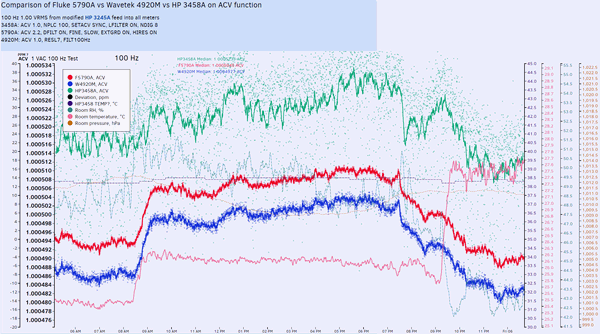
As you can see, actually Wavetek 4920M and Fluke 5790A are pretty close in noise and stability performance. 3458A for AC is much more noisier meter. However as expected, 3458A is multiple times better for DC than 5790A. Wavetek 4920M obviously cannot measure DC at all.
FinalsI was impressed that repaired box with replaced Thermal sensor chip is THIS close, even without full service calibration! It is nearly like replacing ADC in 3458A and finding that readings are still in spec without calibration. Which is cool, but not any help for traceability purposes.
Fluke’s standard calibration is quoted at $5885 USD for 5790A, no wonder cost of such instrument ownership can easily exceed MSRP just few years. Fluke acknowledge this also by providing 2 year specification limits together with more common 24 hour, 90 day and 1 year intervals. Service calibration, which is required after instrument repair or board replacements expected to cost even more. Main reference instrument to calibrate and verify 5790A’s performance is Fluke 792A, calibration of which is $4900 USD. Owner of the instrument will be sending it in for calibration house, to follow up with proper adjustment and verification.
Now I would recommend to all owners of thermal transfer AC instrument not to ever overload them, use correct ranges and limit use of metrology grade standards to calibrate working meters and use those instead for high energy circuits.

This time 5790A got away with just 700$ repair parts (
unofficial!) , next time might be not as easy.

As usual , stay tuned and visit
my site for full article and other fun metrology toys. I also have enough footage for video on my YouTube channel
xDevs_com. Now with 5790A teared down for EEVBlog, I'd need some donations to get Fluke 8508A for post number #4000, lol.