Repaired today my A14 (High-voltage/High-current assembly).
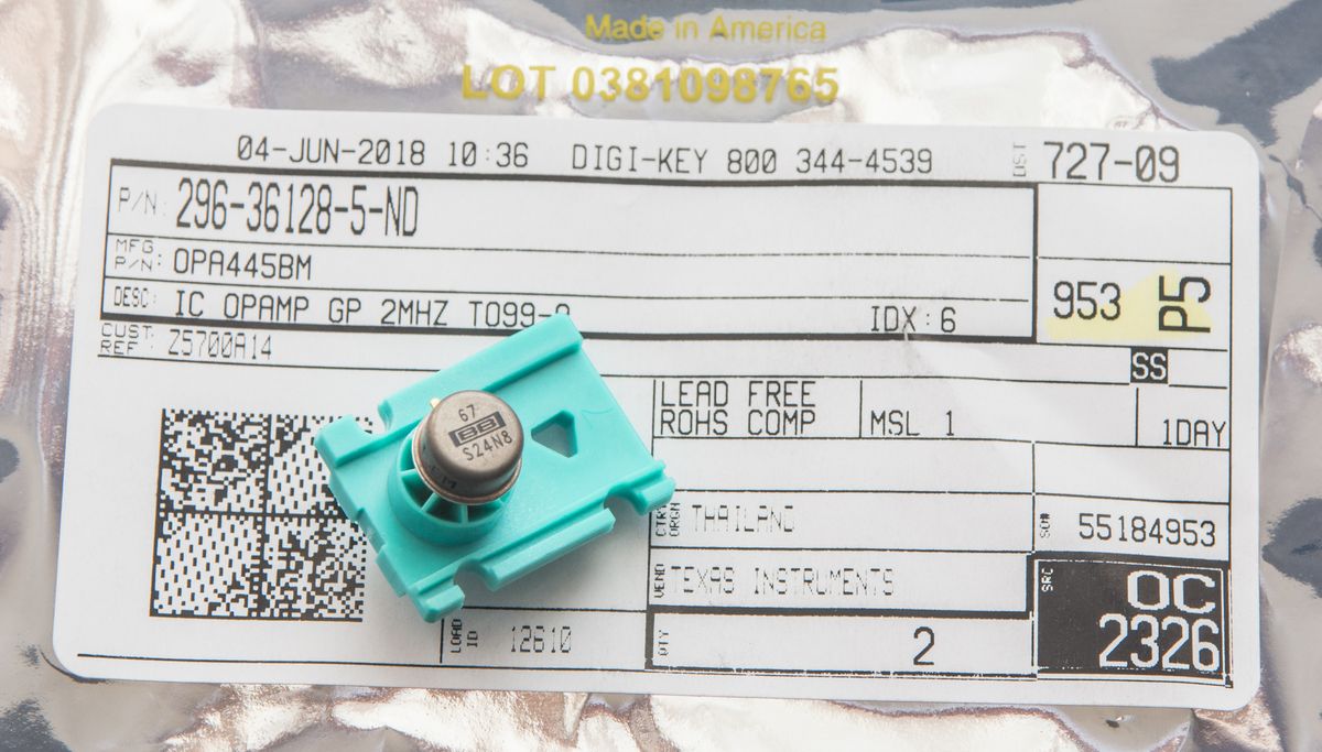
Culprit part was $24 opamp:
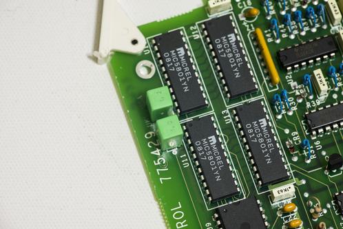
Board overview:
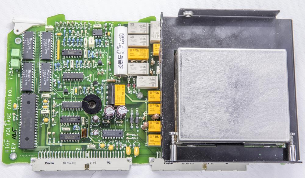
There is I/O and relays control on the right side, A=-100 amp, and other analog circuitry. This board, together with A15 used to generate 1KV DC/AC and 2.2A ranges in calibrator. Big metal thing on the right - is custom transformer made by HIREL SYSTEMS for Fluke (P/N 775288). Transformer was checked to be OK, so that was a "phew" moment.
Original issue was that high-voltage ACV was working, but 2.2A and DCV not, tripping output to standby and failing self-test like:
A15 (HV +DC High voltage output fault) error 3111
A15 (HV +DC/Amp Ref/Error amplitude fault) error 3112
A15 (HV +DC preamplifier fault) error 3109
A15 (HV +DC series pass & current fault) error 3110
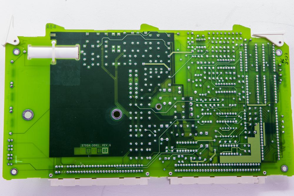
Board received damaged, thanks to "great" shipping

But nothing too hard to fix.
Also because transformer is not tightly mounted to board (it supposed to be fixed by inguard chassis frame, not PCB), it made a dent in board.
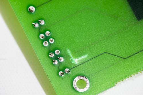
But inner traces still ok, so I'll just let that be.
After some troubleshooting and opamp replacement, she is fully functional now.

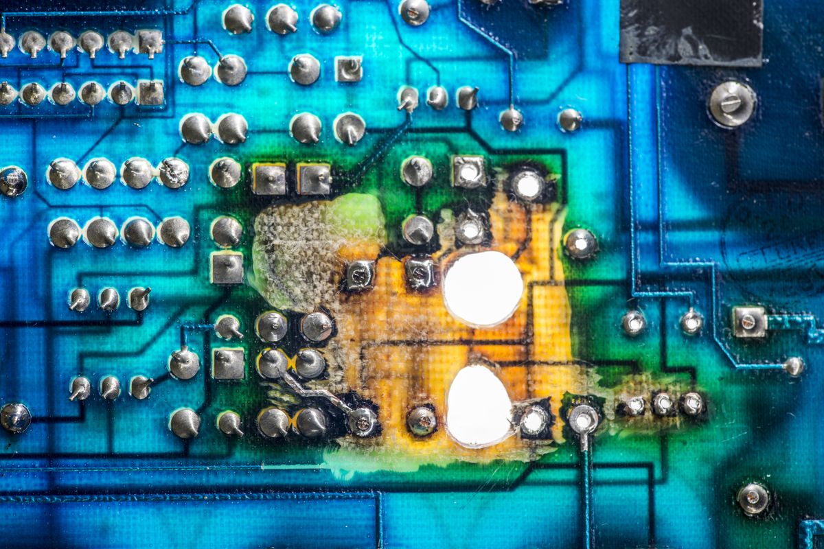
Now I only need to fix my A18, which had one of 220K 3W carbon-composite resistors go boo to 75 ohms and cooked PCB under it.

My strategy is typical - mill out the carbonized FR4 material, restore connections with copper jumpers and put new components (including replacement for all rest carbon comp mines)
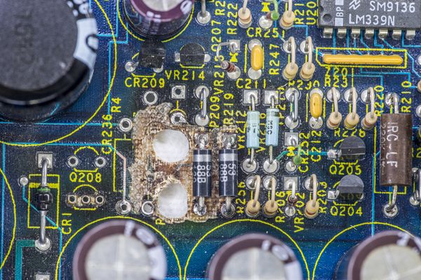
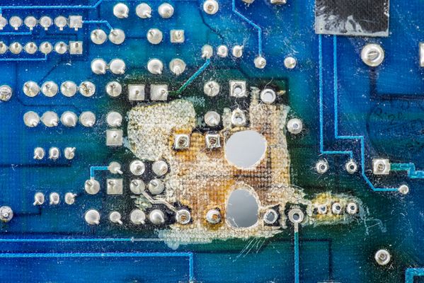
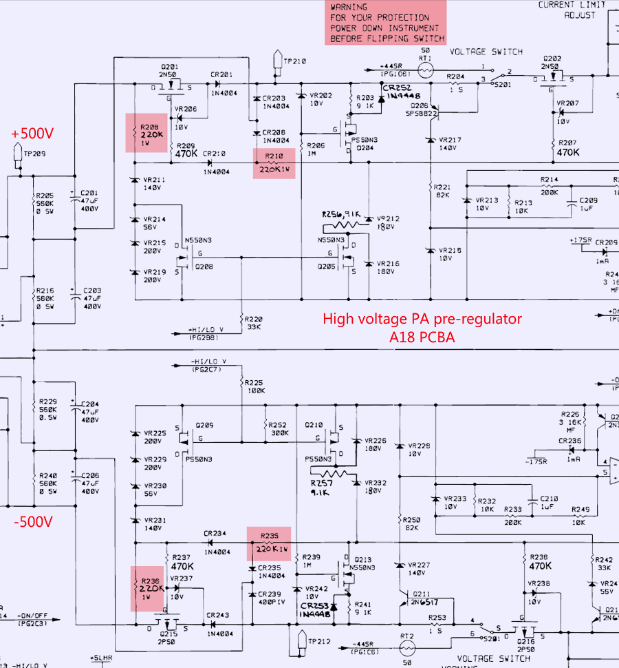
Isolating stuff on this area of the board is bit important, because this is +/-250V supply regulator for MFC's PA.
Schematics of affected area with evil resistors marked out:
To be continued...


