-group-therapy-thread/?action=dlattach;attach=683109;image) I thought I would show my rough dc loads, used to proof test a 28V 35A linear PSU, it powered my 1.2GHz 350W PA for EME.
I thought I would show my rough dc loads, used to proof test a 28V 35A linear PSU, it powered my 1.2GHz 350W PA for EME.
I didn't run them for too long as everything gets very hot esp me! So close to b-f design but mine are much rougher I am afraid.
ROUGH...?!? I'll show you ROUGH. But remember, ya MADE ME!!! 
-group-therapy-thread/?action=dlattach;attach=683544;image)
-group-therapy-thread/?action=dlattach;attach=683550;image)
-group-therapy-thread/?action=dlattach;attach=683556;image)
-group-therapy-thread/?action=dlattach;attach=683562;image)
-group-therapy-thread/?action=dlattach;attach=683514;image)
-group-therapy-thread/?action=dlattach;attach=683520;image)
-group-therapy-thread/?action=dlattach;attach=683526;image)
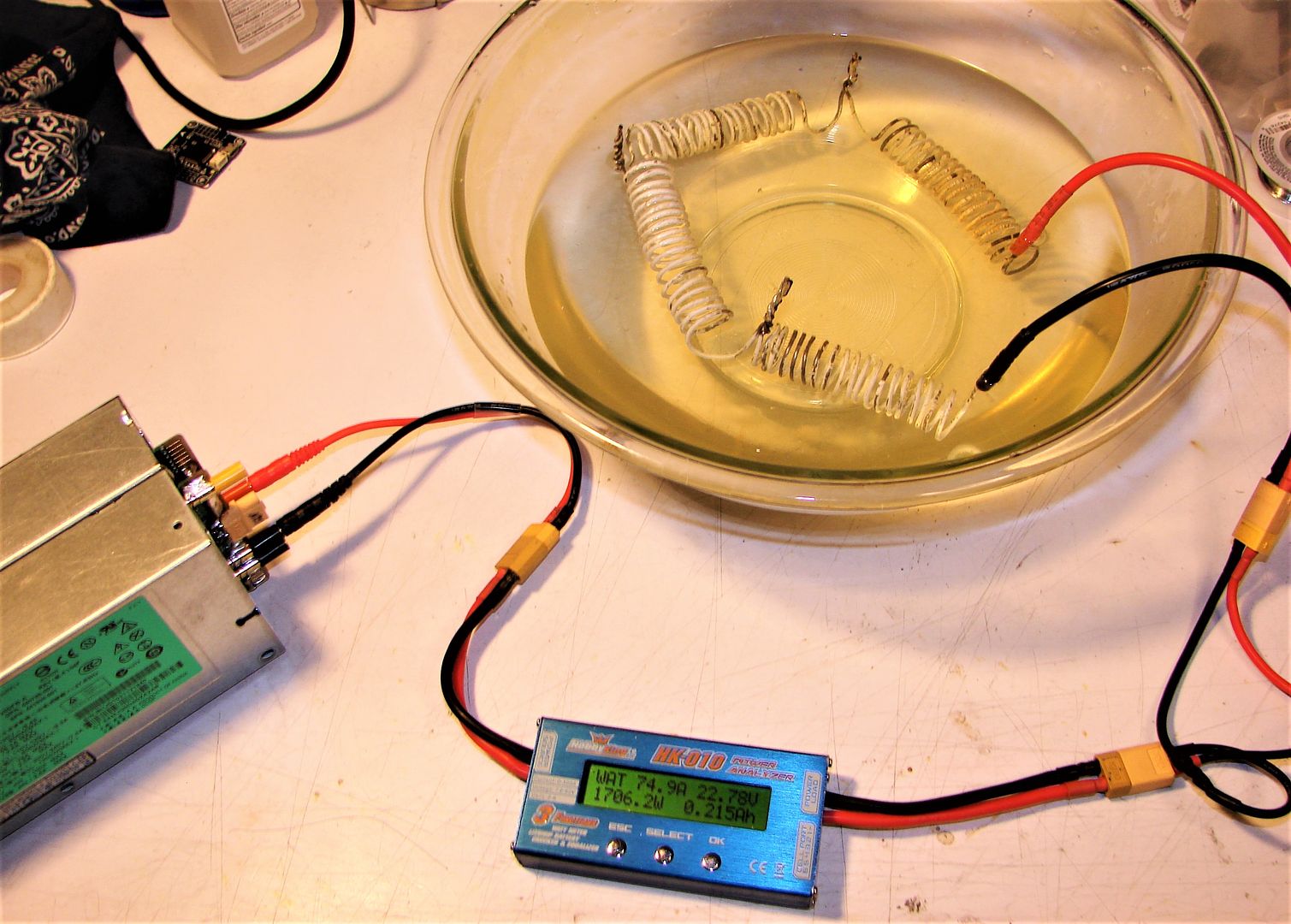
-group-therapy-thread/?action=dlattach;attach=683532;image) And for those who can't live without actual specs; since now I actually have a tool that will tell me:
And for those who can't live without actual specs; since now I actually have a tool that will tell me:Elements are 4 ea of : 1.8mm dia. steel wire wrapped around a 12mm deep socket as a former. Finished 18 turns, ~16mmID/20mmOD, approx 4.5mm spacing between turns. All measurements taken at 20.1°C Ambient. Fresh, cold tap water in bowl, as this is what is used for PSU testing.
1-DC Resistance Dry: 0.27Ω
2-ESR Dry @ 1KHz: 0.281Ω
3-Inductance Dry @ 1KHz: 22.7uH / Q=0.505
4-Capacitance Dry @ 1KHz: 1107uF / tan δ(D)=1.948
5-DC Resistance Wet: 0.24Ω
6-ESR Wet @ 1KHz: 0.259Ω
7-Inductance Wet @ 1KHz: 23.2uH / Q=0.561
8-Capacitance Wet @ 1KHz: 1091uF / tan δ(D)=1.781
Okay... so now you have some baseline specs on my "Coiled Coathanger Ballast Resistor"; you can actually make use of it if you desire. These figures coincide pretty well with the calculated value of 0.304Ω from the demonstration photo above.

I've confirmed in use that bypassing individual elements results in linear current increase, so each element will be 1/4 of these values.
mnem
"Nothing succeeds like excess." ~me


