Siglent permitted to publish their CAD screenshots, this is what they sent me:
The instructions:
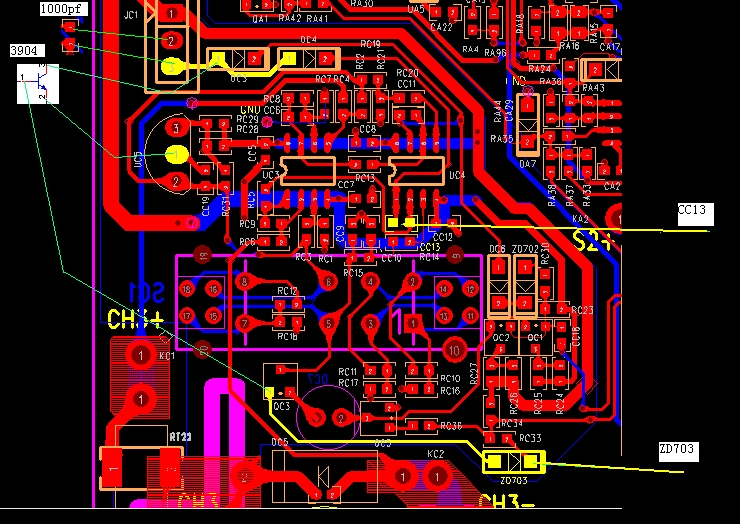
a: add a transistor, model 2N3904(Thru-hole) or MMB3904(SMD), connected as the circuit shows
b: add a 1000pF capacitor, connected between pin 2 and pin 3 of JC1
c: change the ZD703 to the 3.3V zener diode 1N4728A
d: replace CC13 with a 100nF capacitor, in series with a 20k resistor
Step d was a bit complicated, but I managed it by soldering both parts upright at one side of each pad, and then connecting the top sides with a wire. The old CC13 was 100nF, too, so could be used for this step, if it survives the desoldering. I used a new one, just to be sure. 0805 works fine, but looks like the original parts are 0603, but I had already all passive parts in 0805. This is how it looks like:
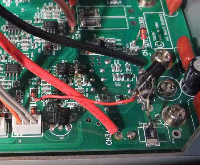
Instead of soldering at JC1, which seems to be soldered to the board, I measured it with an ohm meter and looks like pin 2 of JC1 is connected to junction of the big 0.04 ohm current measure resistor at the bottom and the diode DC5, and to pin 1 of UC5 (the middle pin, bad numbering in the CAD diagram), which made it easier to repair, because I could solder the transistor and the new capacitor at the bottom and use just a wire for the other side of the new capacitor.
This didn't really fix the overshooting, but after some more communication with the support, I got another instruction: Change RC5 to 200 ohm:
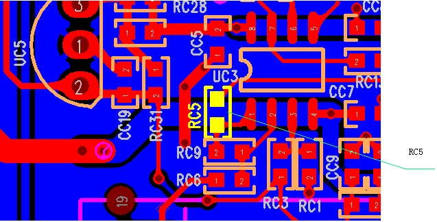
I used 220 ohm, and now it looks (nearly) perfect:
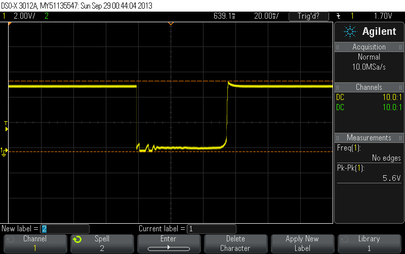
Just to show the effect of the changes, before the repair:
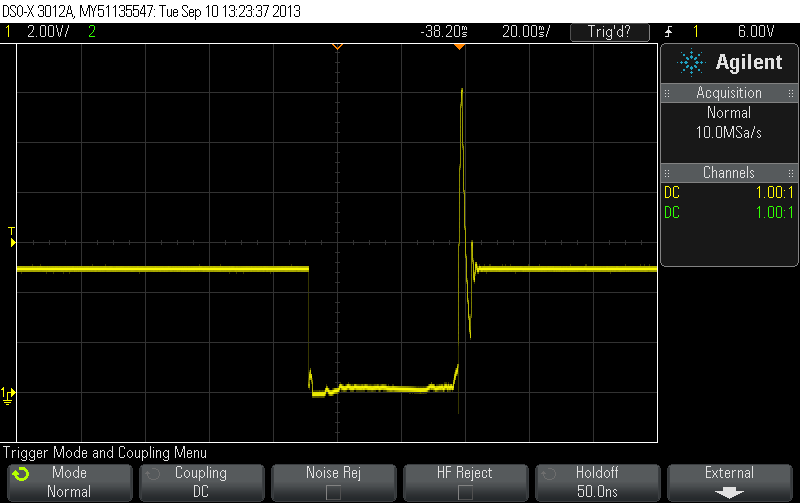
and after the repair:
And the power-on/power-off spike is gone, too.

for Siglent, now I can recommend this power supply without reservations. The support told me that these changes are already included in a new revision of the PSU, maybe ask them which version you get if you don't want to open it and fix it yourself


