I took a P6316 MSO/LA probe apart this afternoon. This is a 16 channel probe designed to work with a number of Tek MSO/MDOs, including the MDO3000 with the MSO option. It can be purchased either with the appropriate option or on its own separately from the MSO option.
http://www.farnell.com/datasheets/1797423.pdfIn the short space of time I've used it on the MDO3000, there are pros and cons.
On the plus side, the cable has colour coded pins adhering to the resistor colour code with just tiny ring clips on each probe end, rather than larger markings sometimes used which get in the way when probing closely spaced and/or dense connections. The 10Mpts is pretty good, I was looking at > 22,000 frame listing of 16 bytes of 50MHz SPI earlier today.
On the negative side, the length of the probe leads isn't great if you operate the scope above your monitor rather than on the bench as I do, it's a choice of either having the cable get in the way in front of the monitor, or try to dress it around the side but then the DUT is placed a bit inconveniently. The sample rate on the digital side on the MDO3000 is marginal for me, at 500MSa/s, occasionally I do look at clock rates just beyond 200MHz in the digital domain. Most irritating is the sluggishness of the scope particularly when dealing with long record lengths. Sluggishness seems to be the order of the day though, even something simple like moving traces up and down has a very noticeable lag on this scope, but I digress.
Back to the P6316 Digital Probe.
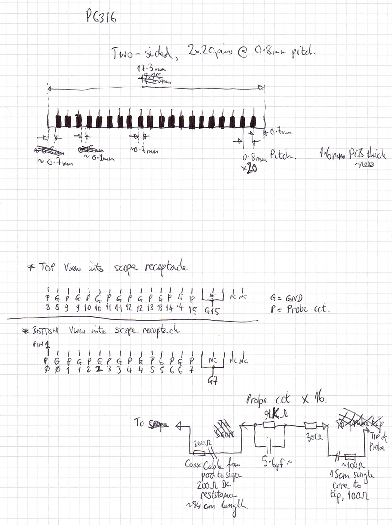
It comprises of a scope connector (40 pin 0.8mm pitch double sided PCB), then two separate ~84cm 8 channel cable pairs to the logic probe interface 2x8 pin 0.1" receptacle. I assumed they were each individually coaxially screened, but on closer inspection there was no visible evidence of this, although the cables are glued down impeding better viewing: they look simply to be twisted pair. Finally there's a short "Lead Set", part number 196-3508-00, for each 8 channel cable, comprising of a 2x8 pin 0.1" mating jack, two 8cm ground leads and eight 15cm probe leads.
Taking each part apart demands some patience with a selection of spudgers. The cases are all two part, and the halves are glued together with a small amount of super glue, so care is needed. The enclosures on the main cable aren't too hard to prise apart but the "Lead Set" box I had to put in a spare 0.1" 2x8 mating receptacle to get enough purchase with the spudgers to prise the halves apart without bending the pins.
Inside the scope end connector there's nothing other than a PCB with the cables connected. Good so far.
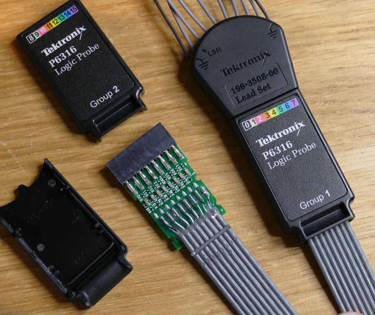
Inside the enclosure at the other end, there's a small passive circuit comprising of two resistors and a capacitor for each channel.
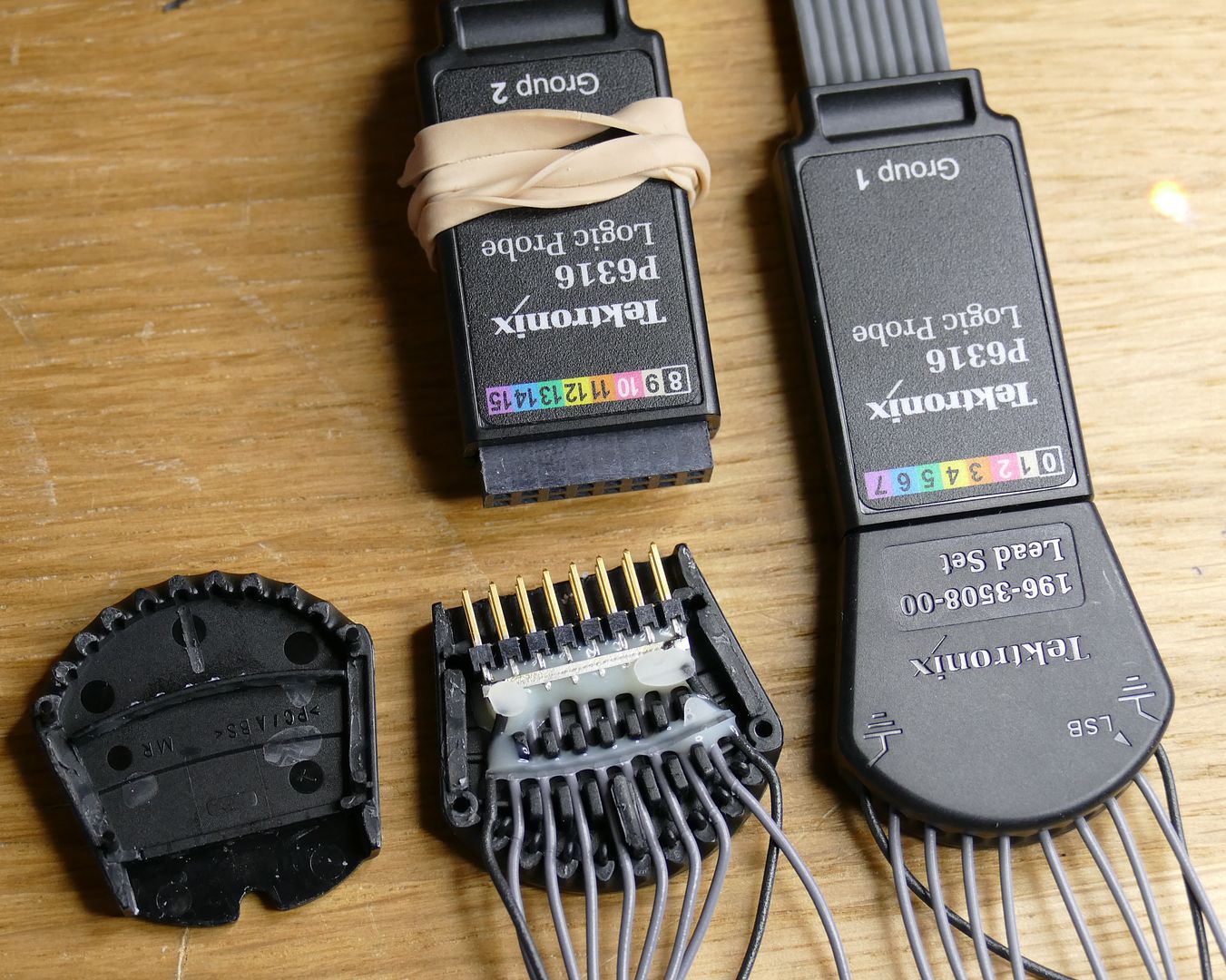
For the Lead Set, there is nothing component-wise.
I also checked to see if there was anything not quite so obvious, as can be the case in scope probe voodoo. It turns out that the 84cm cable has an inline 200 ohm DC resistance on the signal connections, and the 15cm leads on the Lead Sets have a 100 ohm DC resistance. All ground returns are zero ohms.
I would imagine that it would be possible to be able to fabricate a board up to make an old LA probe work reasonably well, the impedance matching and 10:1 factor seem to be similar features between this and Agilent LA probes such as the venerable 54620 probes that are still very common today and are still used on current Keysight MSOs. You might even get away with fabricating an entire probe, but that inline resistance is in there for a reason, there's a really old Tek document about it somewhere that I can't locate right now, but it's also covered here
http://www.dfad.com.au/links/THE%20SECRET%20WORLD%20OF%20PROBES%20OCt09.pdf. I don't know if the Agilent/Keysight probes have this distributed resistance too, they do have a fancy woven cable on the two examples I have so I wouldn't be surprised.
Teardown...Scope connector, nothing much to see here other than 0.8mm pitch, double sided PCB connector.
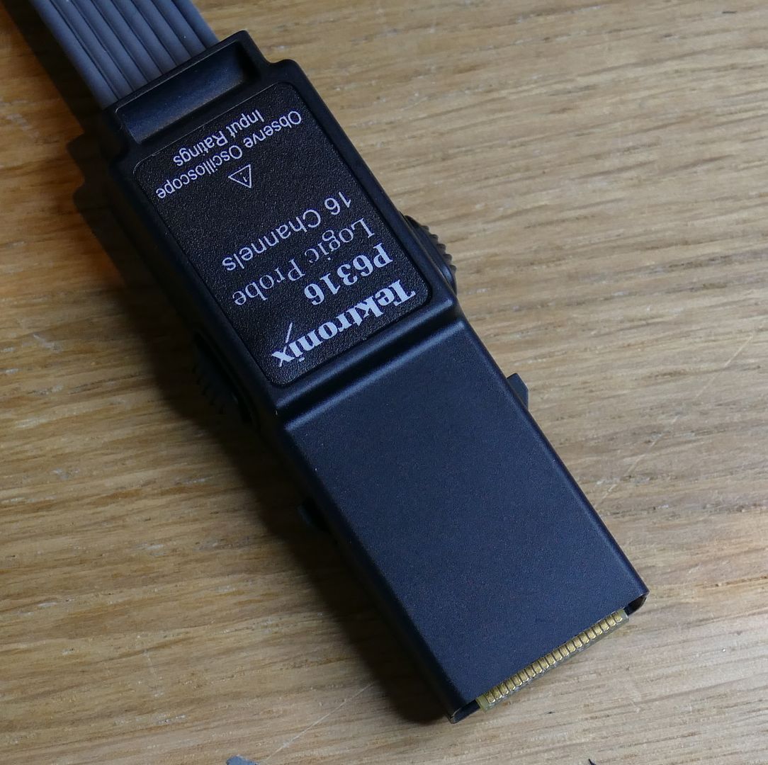
Top of scope connector is for group 2 inputs, D8-D15
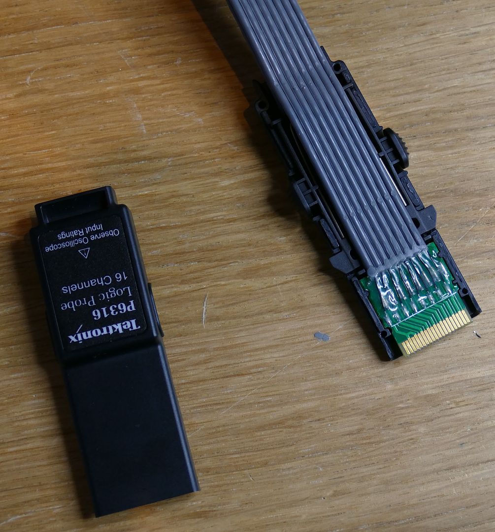
Bottom of scope connector is for group 1 inputs, D1-D7
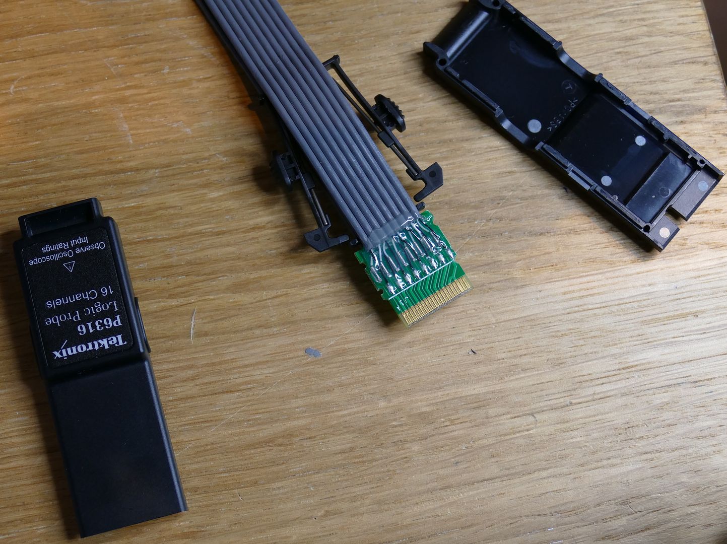
Top of one of the two probe ends of scope lead, showing the three passives.
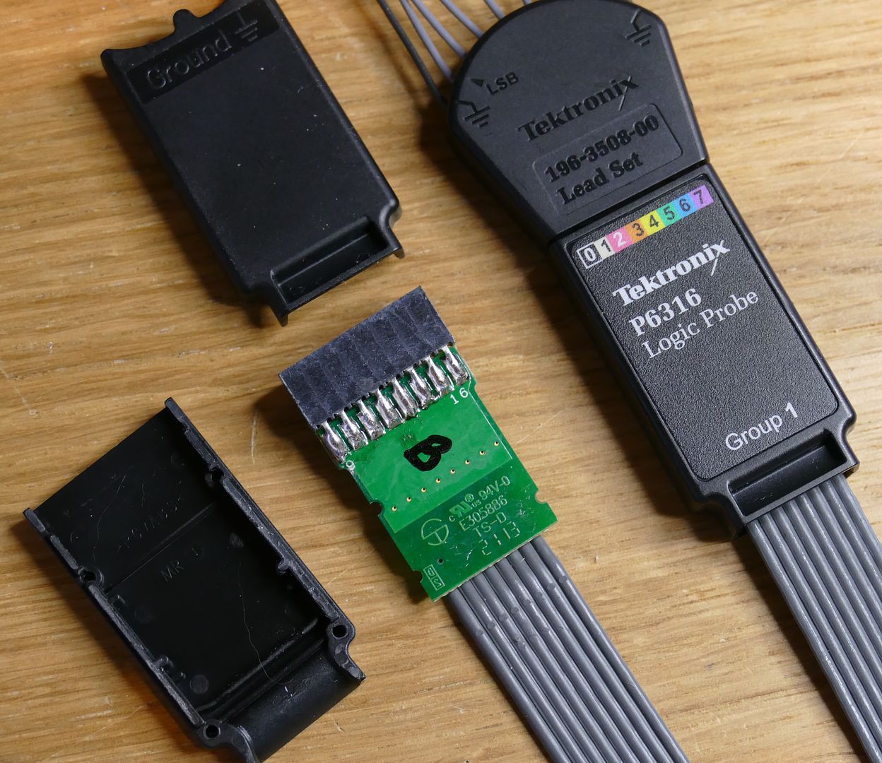
Bottom of one of the two probe ends of scope lead: the "B" was written on by me, but the soldering is a bit "how you doin'"
Top of the "Lead Set"
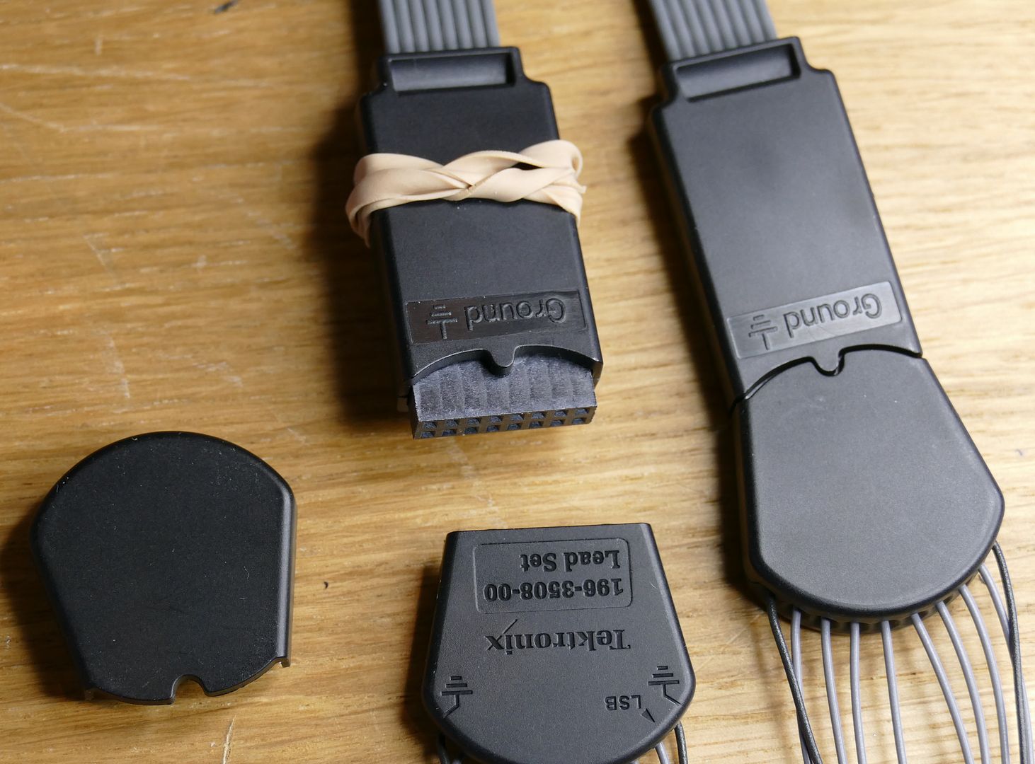
Bottom of the Lead Set for completeness, I didn't take this bit apart, too much glue to take off and re-apply.
DaveCAD
