Author Topic: Juntek DPA-2698 10Mhz signal amplifier + digilent analog discovery  (Read 5475 times)

0 Members and 1 Guest are viewing this topic.

Offline Dip_SwitchTopic starter

  • Newbie
  • Posts: 3
  • Country: de
Hello eevblog.

While playing with a digilent analog discovery I found out that the output current is too much limited. The Waveform generator output AD8067 is limited by one/two PTC thermistors providing thermal protection in case of an output shortcut. PRG18BB470MB1RB 47 Ohm PTC Murata  hold current 14mA / hold current2 29mA. It happened while measuring that the PTCs became high ohmic.
(When I made the BNC/SMA/impedance adapter I added an additional 50 Ohm resistor to the existing waveform generator's output 47Ohm PTC....maybe unnecessary ....maybe not)

So I decided to add the signal amplifier DPA-2698 from juntek/ 58Euros shipped.


analog discovery adapter wiring with AC/DC / 50 Ohm impedance/ GND disconnect/ impedance measurement resistors jumpers:
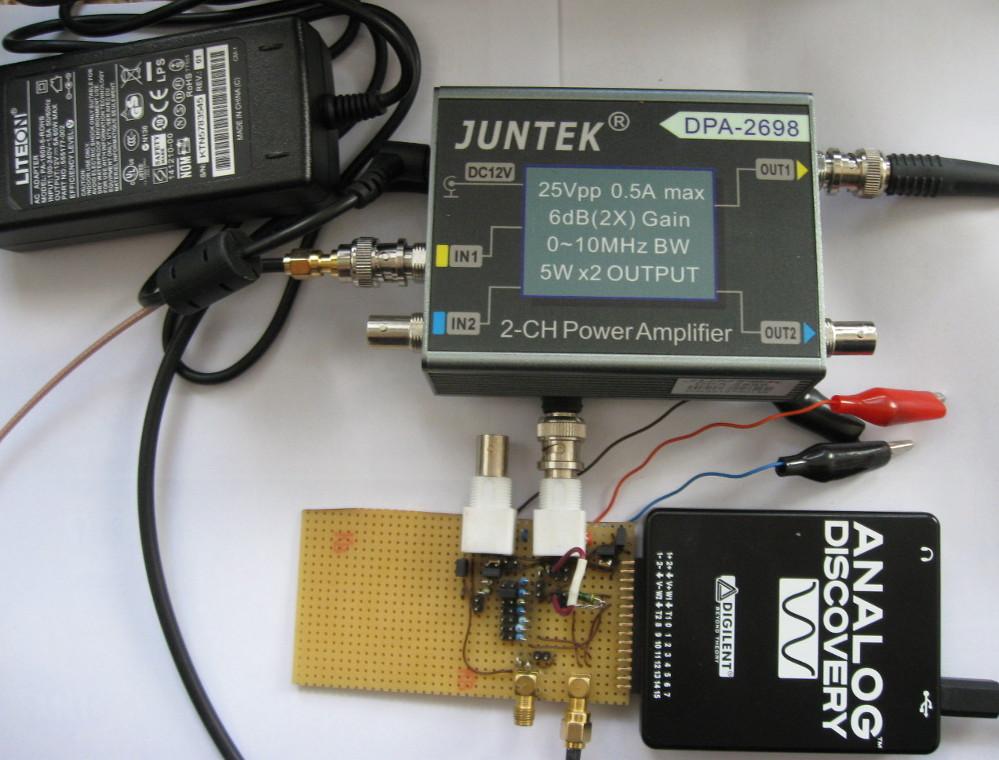


Juntek DPA2698:


Juntek DPA-2698
Signal Bandwidth:0-10MHz
Input Voltage Range:0-20Vpp
Output Voltage Range:0-25Vpp
Voltage Gain:6dB (double amplification)
Output Maximum Current:0.5A
Maximum Output Power:5W*2
Output Impedance:≤5Ω
Output Phase:In phase with input
Distortion:≤1%
Flatness of Output Signal:±1dB
Input Power Supply Voltage:DC12V±10%
Input Maximum Current:5A

parts used inside:
BUF634F  x4 , 250mA output current each
something like OPA810 x2,  4 resistors for gain control
XL6012E1  x1   produces +15/-15V out of 12V input voltage 
Fan 12V 30x30x10.5mm
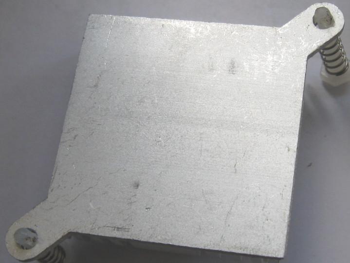
heat sink 37x37mm

Texas Instruments offers an evaluation module BUF634AD maybe this was the inspiration for the DPA-2698

BUF634 data sheet
BUF634 250-mA High-Speed Buffer
output current: 250 mA
Slew rate: 2000 V/µ s
Pin-selected bandwidth: 30 MHz to 180 MHz
Low quiescent current: 1.5 mA (30 MHz BW)
Wide supply range: ± 2.25 to ± 18 V
Internal current limit
Thermal shutdown protection

OPA810 140-MHz, Rail-to-Rail Input/Output, FET-Input OP Amp
Gain-bandwidth product: 70 MHz
Small-signal bandwidth: 140 MHz
Slew rate: 200 V/ µs
Wide supply range: 4.75 V to 27 V
Input voltage noise: 6.3 nV/ √Hz (f = 500 kHz)
Input current noise: 5 fA/ √Hz (f = 10 kHz)
Rail-to-rail input and output:
FET input stage: 2-pA input bias current
High linear output current: 75 mA
Input offset: ± 500 µ V (maximum)
Offset drift: ± 2.5 µV/ ° C (typical)
Low power: 3.7 mA/channel

 
XLSEMI
XL6012  180KHz 60V 5A Switching Current Boost DC/DC Converter               
Wide 5V to 40V Input Voltage Range
Maximum Boost Output Up to 60V
Maximum 5A Switching Current
SW PIN Built in Over Voltage Protection
High efficiency up to 94%
Built in Thermal Shutdown Function
Built in Current Limit Function


There was no thermal paste under the BUF634F  heat sink.


I attached parts of the DPA2698 schematics:


4 resistors determine the OPA810 gain=Ua/Ue=R2/(R1+R2)*(1+R4/R3)
R1=R2=R3=1K / R4=3K
So the gain is set to   
gain=Ua/Ue=R2/(R1+R2)*(1+R4/R3)= 1K/(1K+1K)*(1+3K/1K) = ½ *(4)
=2   , R4 could be replaced by a 10K trim poti
gain(R4=1K)=1
gain(R4=7K)=4


DPA2698 data sheet claims:
Output Voltage Range:0-25Vpp 
 
If you want to use the BUF634F in a Voutput range of +/-10V the output current should be  limited by 170-180mA if the BUF634F is hot at Tj= 125 Degrees Celsius. Vinput then should be around +/-13V. At least the curve in the data sheet makes use of 13V.

I measured +13,5V Output Voltage at +12,5V Input Voltage. 
So a realistic 0,17A per BUF634F load Output Voltage range is Vpp=20V
Under no load Vpp could be even 26V.


DPA2698 gain linearity from 1Hz-10Mhz:
Signalgenerator used was the analog discovery wavegen. 
wavegen output 0,5V

1)built in wavegen without DPA2698--> gain loss  = -3,235dB at 10Mhz

2)using built in wavegen + DPA2698  without bias --> gain loss  = -2,6588dB at 10Mhz

More accurate measurements are not possible currently.
Yes, I know my drawings are überbeautiful.
Measurements were made without 50 Ohm impedance matching.


The system does not cost a world, limited to 10-20Mhz but I like it.
and I can measure the capacities of Gold Caps even using bias voltages!


Greetings.
Dip_Switch
« Last Edit: May 14, 2020, 01:51:51 pm by Dip_Switch »
 
The following users thanked this post: Mark, egonotto, kado, TurboTom, ledtester, maxwell3e10, grandsons, Grauwacke

Offline Grandchuck

  • Frequent Contributor
  • **
  • Posts: 683
  • Country: us
Re: Juntek DPA-2698 10Mhz signal amplifier + digilent analog discovery
« Reply #1 on: May 03, 2021, 02:08:51 pm »
Been playing with one of these and thought to share some observations.  The built-in negative supply is a tad weak: it measures -14.7V which drops to -14.4V when the amp is supplying 5 volts RMS to an 18 ohm load.  The built-in +15V supply is accurate and has good regulation.

It was easy enough to tack on an external supply as shown in the attachment.  The performance with a bench power supply is a tad better but still not what I expected.  When supplying 3.5 V RMS @ 1 kHz to the 18 ohm load, the THD is 0.3 %.  The attached graph shows MUCH better performance than that.  That graph is for the upgraded version of the amplifier IC (the A version).  I cannot find any THD specs for the old version of the IC?

The BW is 10 MHz and, generally speaking, it is still a useful device.
 
The following users thanked this post: egonotto

Offline mawyatt

  • Super Contributor
  • ***
  • Posts: 3564
  • Country: us
Re: Juntek DPA-2698 10Mhz signal amplifier + digilent analog discovery
« Reply #2 on: August 26, 2021, 04:03:09 pm »
The one we have the amp packages have been laser erased. These are a decent amp, as are the lower frequency higher power DPA-1698, and both are very reasonable $. We also created a custom HV version capable of 180VPP based upon the OPA462, to allow our AWG to reach these higher voltage levels.

The reason for the drooping of the negative supply voltage under load is due to the nature of the way the negative supply is created. This is a charge pump inverting type working off the diode commutating voltage which creates the positive supply, thus the negative supply is not directly regulated but inferred from the positive supply.

Best,
Curiosity killed the cat, also depleted my wallet!
~Wyatt Labs by Mike~
 

Offline voltsandjolts

  • Supporter
  • ****
  • Posts: 2350
  • Country: gb
Re: Juntek DPA-2698 10Mhz signal amplifier + digilent analog discovery
« Reply #3 on: August 27, 2021, 03:54:19 pm »
The mains power supply provided with the unit is a UL listed Liteon unit, which is good, assuming its genuine :P

Regarding the amp itself, the aluminium case is nice.
Some solder joints needed minor rework and components leads needed trimmed - they were close to touching the base of the metal case.

I'm a bit surprised the feedback for the LM7171 doesn't come from the amplifier output connection, instead they have just taken it from the output of the LM7171 itself.
The datasheet for LM7171 recommends a few pF across the feedback resistor, for stability. I see the output level increases above 20MHz so I might try their recommendation.
The quiescent current of the BUF634's could be reduced since their full bandwidth is not required, but that also reduces PSRR a little too.

The worst thing about this unit is noise on channel 1 coupled in from the fan.
The PCB layout is poor and the input divider trace passes right by the fan connector.
This can be solved with a 100nF 0603 on the fan connector pins, on underside of the PCB.

There is also some 180kHz switching psu noise spikes on the outputs.
CH1 suffers worse as it's closer to the regulator circuitry and on my unit I see 40mV spikes on the output, with the input grounded through 50 Ohm.
Not a big deal for me since I use it as a power amp, not a precision amp.

At this price I doubt the BUF634s or LM7171 are from a reputable source, which might explain the half-hearted attempt to erase the device markings - to avoid any potential import embargos of counterfeit devices. Or maybe I'm just getting old and cynical ;D

PDF schematic attached.
« Last Edit: September 11, 2021, 11:03:31 am by voltsandjolts »
 
The following users thanked this post: Mechatrommer, hfleming, ledtester, Grandchuck

Offline voltsandjolts

  • Supporter
  • ****
  • Posts: 2350
  • Country: gb
Re: Juntek DPA-2698 10Mhz signal amplifier + digilent analog discovery
« Reply #4 on: September 18, 2021, 01:00:31 pm »
I added 2pf across the feedback resistor and it does prevent peaking I was seeing at 20MHz and above.
Not too much effect on the passband response - plot shown had 50R load, and was using genuine TI LM7171 that I had lying around.
« Last Edit: September 18, 2021, 03:57:02 pm by voltsandjolts »
 
The following users thanked this post: hfleming


Share me

Digg  Facebook  SlashDot  Delicious  Technorati  Twitter  Google  Yahoo
Smf