I have been hunting for a 1GHz+ scope for over half a year. I prefered one which has a high enough samplerate to do this in a single shot. Ofcourse it is 'easy' to spend several $k on a Lecroy Wavepro 7000 series or something similar but I didn't want to spend that much and avoid too much overlap with the oscilloscopes I already have. The older Lecroy LC584 is also interesting and I nearly got one but the Ebay seller bailed out on me (I did got a refund though). I also looked at the Tektronix TDS694C and TDS784 but the problem with these scopes is that they are older than the Agilent 54835A, have an obsolete NVRAM (SRAM + battery) inside and need special calibration software. The 54835A OTOH can calibrate itself using the auxilary output so it doesn't depend on calibrations values or options stored in a NVRAM. Big plus! My main application for the 54835A is looking at high frequency signals (digital and analog). The 54835A has a maximum depth of 65kpts on 2 channels and 32kpts on 4 channels and no peak-detect. I guess that if you don't want to spend much then deep memory and peak-detect are out of the window. OTOH the 54835A has a lot of tools for signal analysis like FFT, color grading and stacked/chained math functions.
After some haggling and waiting I got this one from an Ebay seller called express_test:
First I would like to point to this nice page with a different repair job on a similar scope:
http://www.dasarodesigns.com/projects/fixing-an-hp-agilent-54845a-infinium-oscilloscope/ It has many details on the circuits.
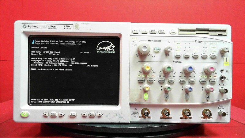
The most appearant problem is that it doesn't boot but otherwise it is a complete mistery. The upside is that the hard drive is detected which means it spins up and likely still has the software on it.
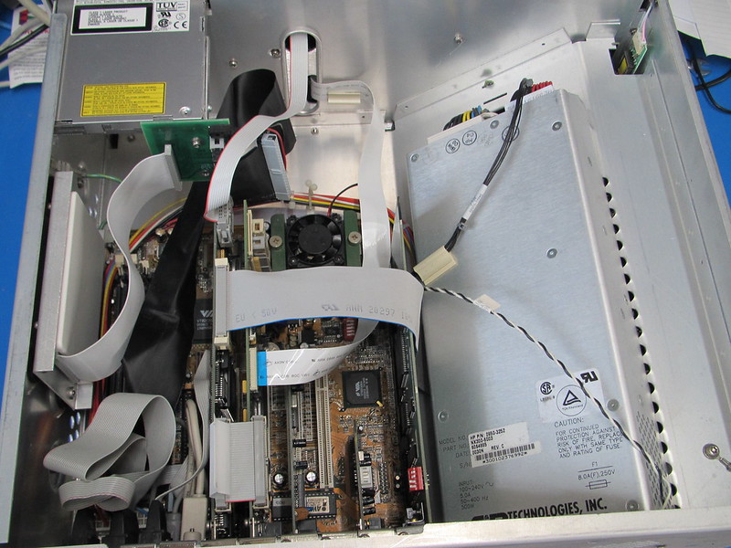
I opened it first to check whether all the wiring is connected and there are no potential safety issues.
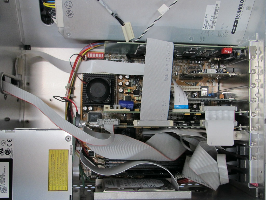
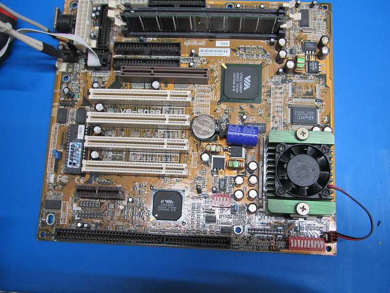
Some pictures of the inside. First the part where the PC lives. Inside there is a VA503-A Super Socket 7 motherboard from FIC with an AMD K6-2 400MHz processor and 64MB of SDRAM memory.
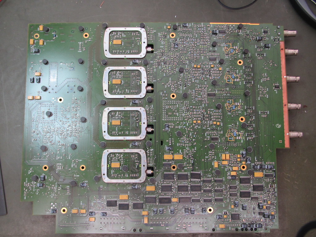
The acquisition board is at the underside. This is also where most of the airflow is directed.

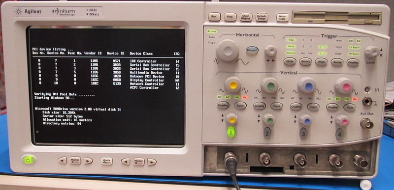
Time for firing it up for the first time. With a PS/s keyboard connected I got passed the BIOS error message and after a short while the firmware started. The scope runs on Windows 98 (first edition). After a quick check it turned out (only) channel 2 is not working. All in all the noise isn't as bad as I had expected seeing the two 120mm fans. The high pitched whining noise from the hard drive is way more irritating.
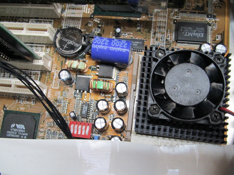
Time to take try and fix itChanging the battery (which was empty) helped to get rid of the BIOS error and made the scope boot without needing to press a key. Note the bodge capacitor!
The first thing I wanted to try is to swap the attenuators. From the service manual I learned that the probe connector panel had to come off before the BNCs of the attenuators can be unbolted. Unfortunately this means peeling the sticker off before the screws which hold the panel can be reached. That didn't work out very well:
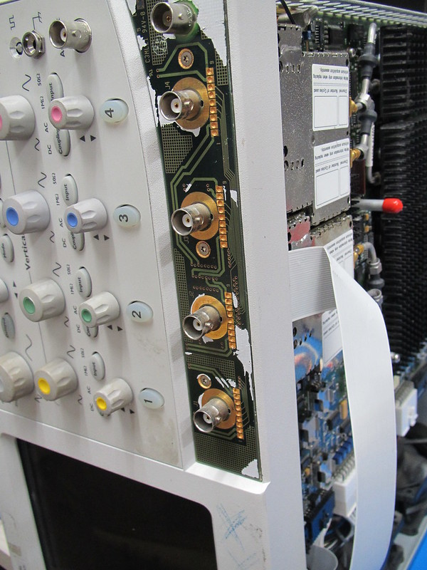
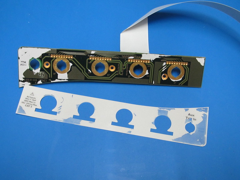
I think it will still look reasonable when put back together again.
Some further disassembly:
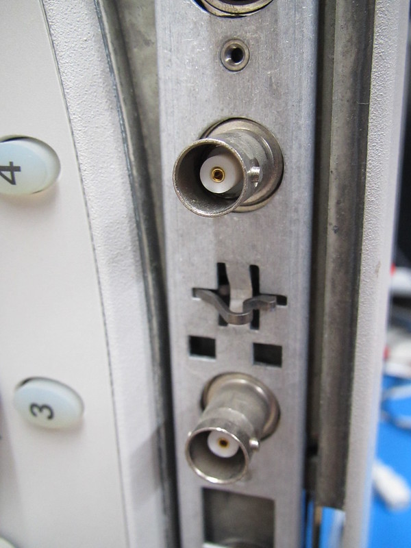
A spark plug socket for a socket wrench fits nicely on the BNC's nuts BTW.
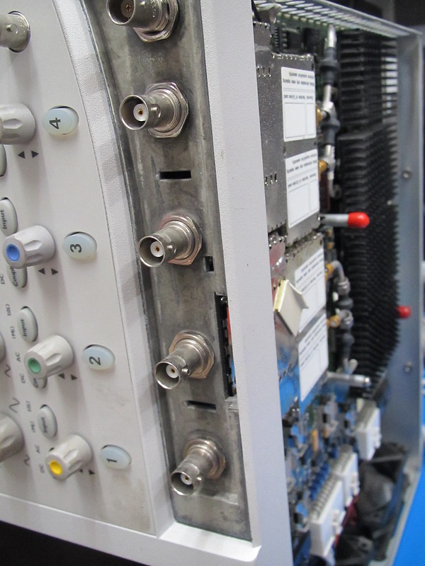
After swapping the attenuators it turned out the problem still persisted. Not happy! In the next step I swapped the ADC hybrids between channel 1 and 2:
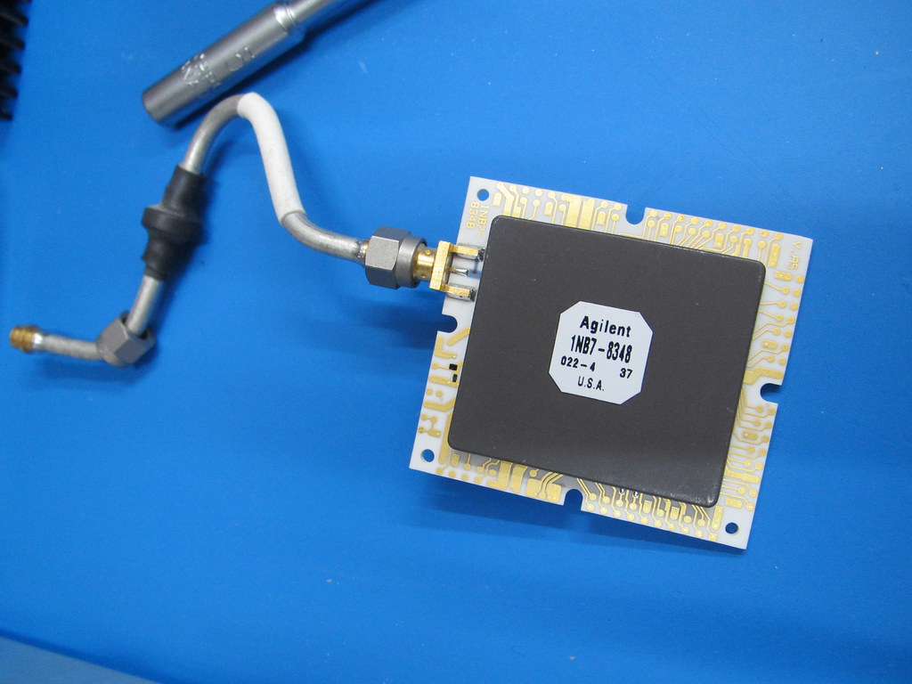
The ADC hybrids are connected to the board using some sort of socket with pogo-pins (spring loaded pins) which make contact between the ADC hybrid and the board. Ofcourse I cleaned everything with alcohol. Still no luck though. The problem moved with the ADC hybrid. In a final attempt to rule out any other problem I cross connected the attenuator outputs using SMA cables.
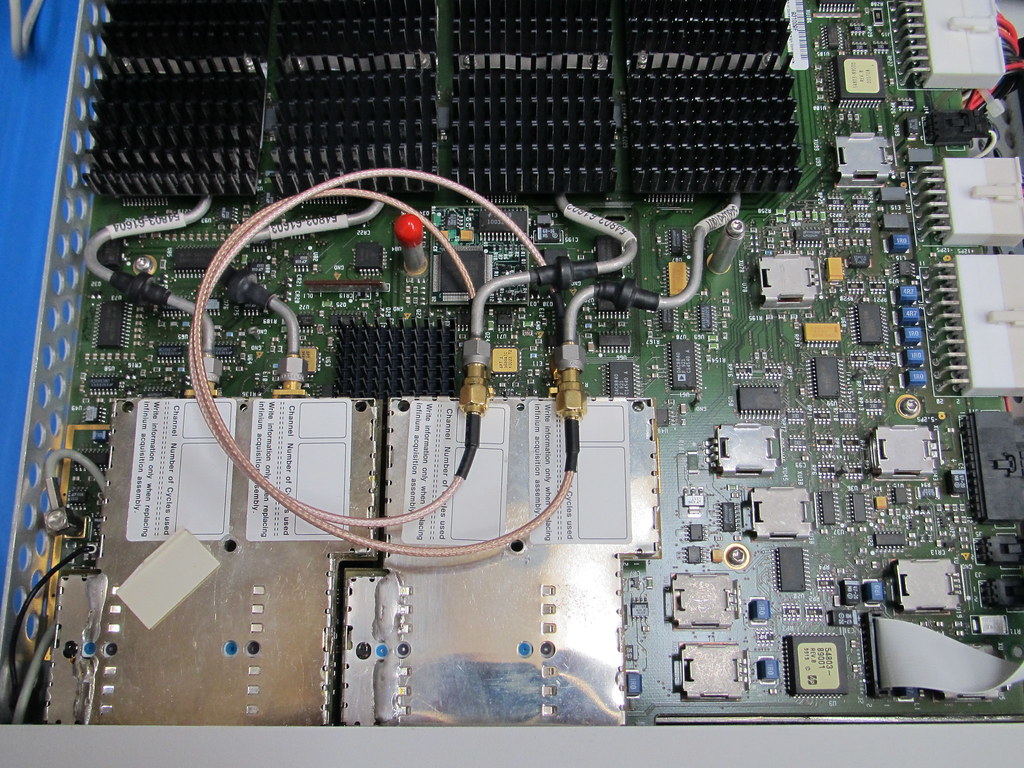
Still no go so the only conclusion is that the ADC hybrid which is now on channel 1 is broken. I managed to source a module for (what I think) is a reasonable price but I have not received it yet.
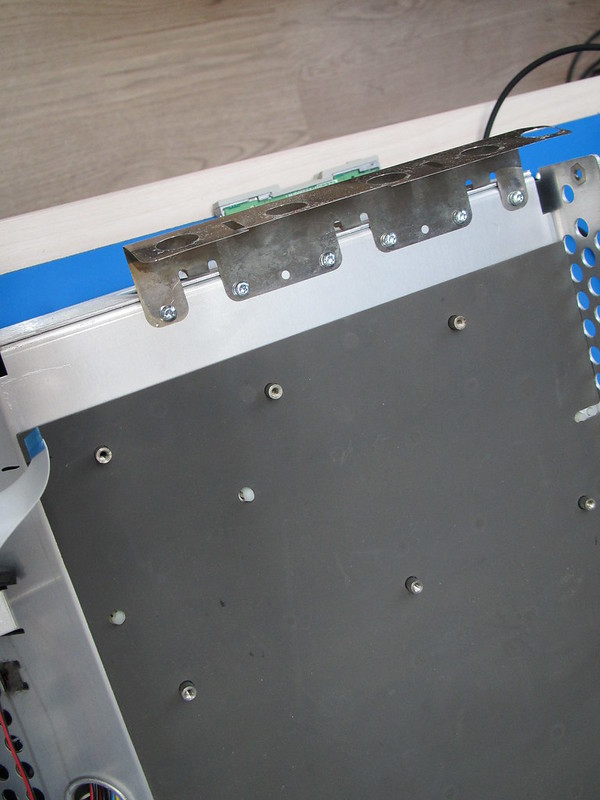
After this I ran a full diagnostic which also pointed to some errors in the trigger circuit. Maybe it has been damaged because a piece of shielding metal wasn't fixed to the frame. Here is a picture which shows the shied re-attached to the frame using some M3 screws:
When browsing on the hard drive I found an interesting help file: HP4XS.HLP . This seems to contain a partial guide to do component level diagnostics/repairs. Hopefully it is helpful if it turns out the trigger circuit is really defective.
CleaningWith nothing else to do let's give the outside a thourough cleaning to get rid of the grease marks and sticker residu. Much better if I may so so:
 Hard drive image
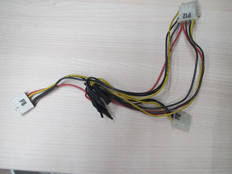
I have not been able to find any older versions of the software for this oscilloscope so I made a backup using Ghost. For this I needed to connect an extra hard drive. The problem is that there are no power extension leads to do this so I made one out of the wires from an old AT power supply. The VA503-A motherboard has both AT and ATX style power connectors and the AT one isn't used but suitable to drain some power from.
After this creating an image was easy.
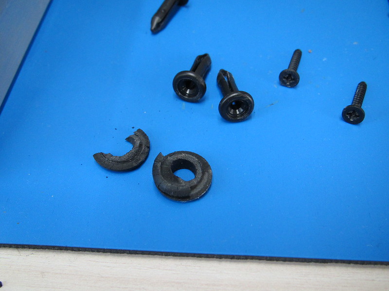
Rubber fan mountingsThe rubber fan mountings where completely perished and I have a bag of leftover cable glands.
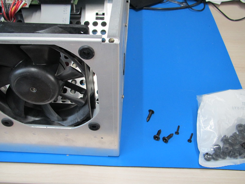
I like to think this made an improvement.
Time for some uphacking!I already knew from the service manual that the hardware for the 54835A, 54845A (1.5GHz 8Gs/s) and 54846A (2.25GHz / 8Gs/s) is exactly the same so there had to be some option strappings to set the model. Forum member Jwalling pointed me towards some resistors on the acquisition board which set the type of oscilloscope. The bad thing is that these resistors are on the solder side of the acquisition board so I had to take the entire board out.
The board is covered with a rubber-ish RF shielding slab.
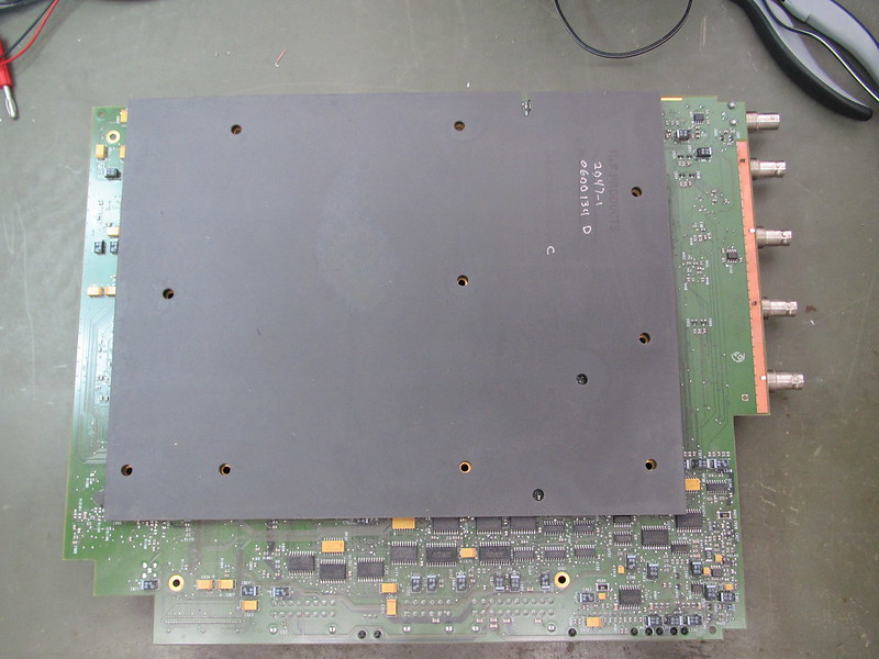
After removing the RF shielding:
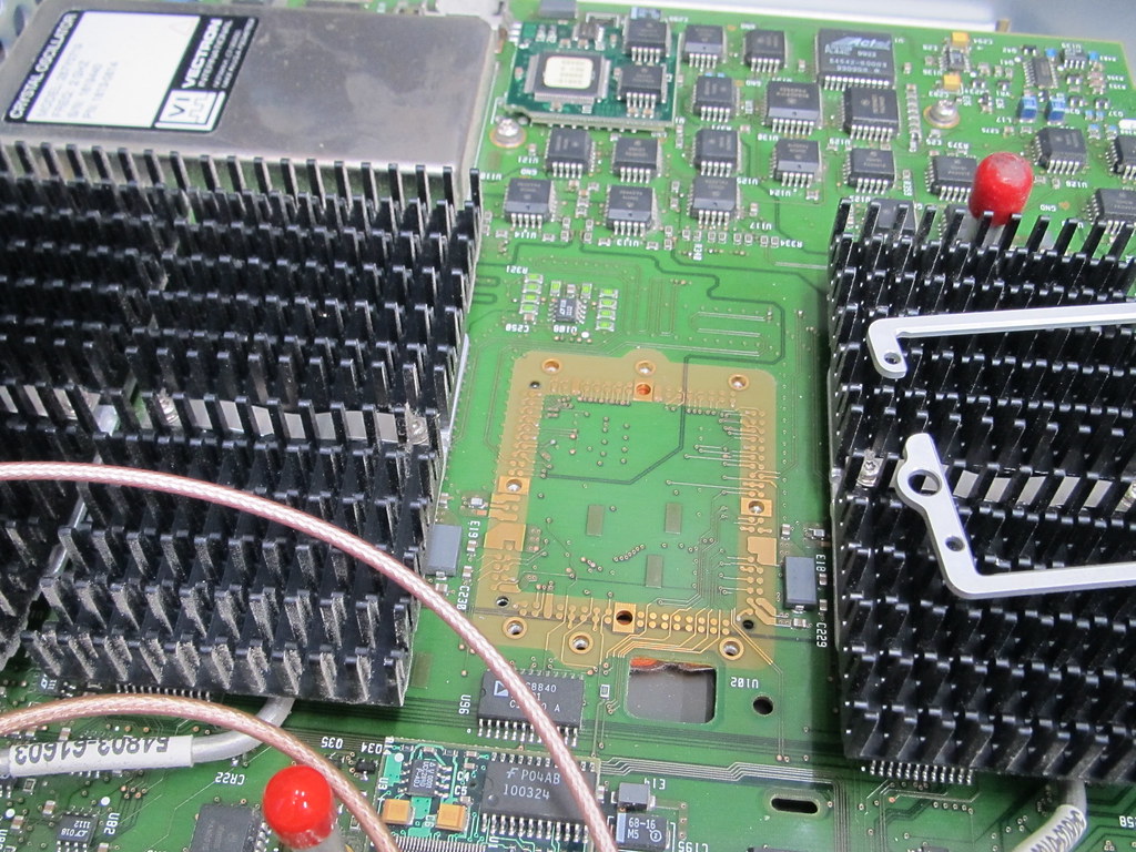
When glancing over the board something odd caught my eye and I had a WTF! moment:
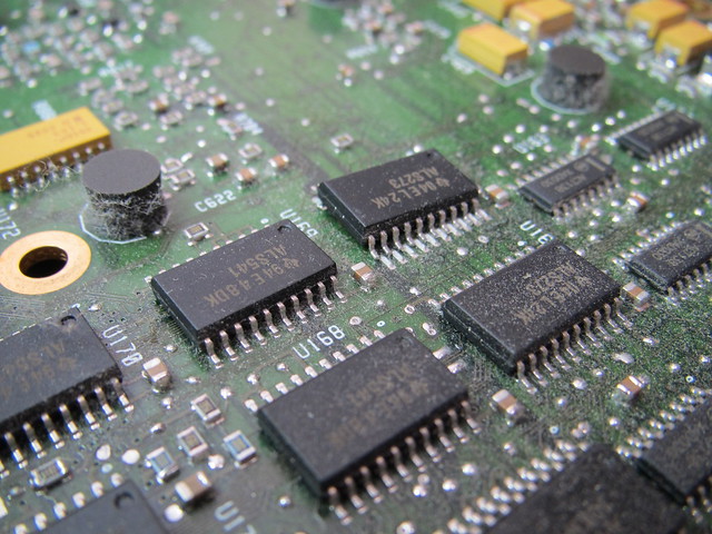
This chip isn't attached to the board except with one leg! Some flux and solder fixed that but oddly enough it didn't seem to have any effect on the errors the self test showed.
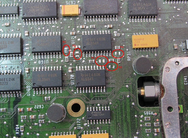
Back to the uphacking part. I located several resistors and decided to attach some switches after a few futile attempts to change the resistors using SMT tweezers.
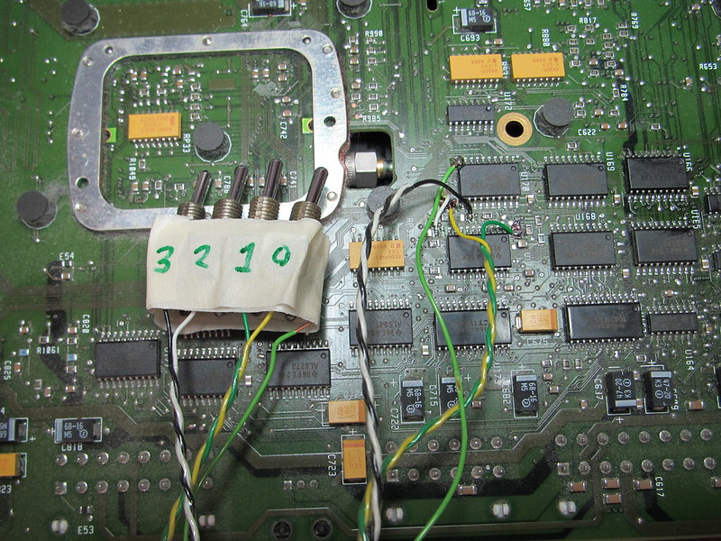
The scope software can be stopped using ctrl-alt-del which opens up the task manager on Win98 and restarted from the menu so testing all the combinations could be done quickly.
R3 R2 R1 R0
-  -  X  X  54835A
X  X  -  -  54845A

X = placed, - = open
I have not found the 54846A mode but I have not included R4 in my test because I didn't spot it when looking for potential candidates. For now I'm fine with the 54845A mode.
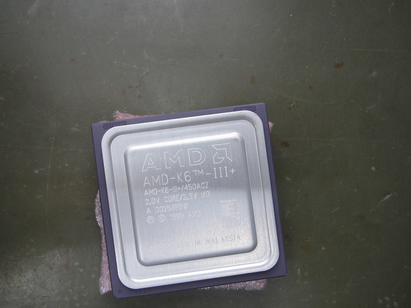
There where also two other things on my wishlist: more memory and a faster processor. Much to my surprise FIC still has an FTP server with documentation and BIOS files
ftp://ftp.fic.com.tw/motherboard/. How cool is that? From the documentation I learned the maximum memory is 768MB divided over 3 modules of 256MB each. It also should support the AMD K6-3 450MHz processor which (ofcourse) is faster and according to legend among the fastest socket 7 processors ever made. So I went on Ebay and spend $18 +shipping on 3 256MB memory modules and $15 on an AMD K6-3 450MHz. The memory was advertised as new but I got 3 different modules and anti-static bags so I'm quite sure these are pulls. But hey, they where only $6 each. The biggest SDRAM module I had in my pile is 64MB so I guess back then 256MB ones would have been insanely expensive. The AMD K6-3 450MHz however did look brand new:
Installing the memory was straightforward. The processor proved more difficult. First of all I needed to dig up a Pentium-I cooler from my scrap heap because the original heatsink is glued onto the processor. Secondly with the new processor installed and setting the right core voltage & multiplier it wouldn't boot. Drats! After some Google-fu I found a forum message from the beginning of this millenium saying FIC has a beta BIOS version which supports the K6-3 450MHz. I found this in FIC's FTP server with version number JN4116. However the current BIOS version on the motherboard said JN4204 which I couldn't find in FIC's archive so this could be a special Agilent version. I also would expect version 4204 to be newer than 4116. I decided to give it a try and save the old version twice (and check!) before attempting to flash the BIOS with version 4116. End result: BIOS version 4116 works with the AMD K6-3 450MHz and so does the oscilloscope software! The performance increase (waveforms/s) is about 15%.
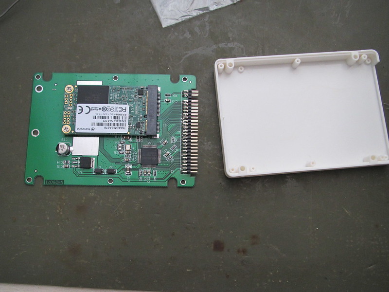
Running Windows XPThe PC part is powerful enough to run XP. There are three advantages of XP: it supports USB sticks, it runs the processor cooler and it can run the latest version of the software I found. Part of the process is also to install an SSD consisting of an mSata module in an mSata to 44pin IDE converter:
I also needed a CD-ROM drive so I threw that into the mix as well:
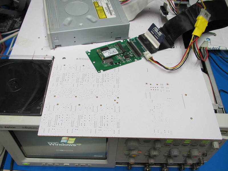
While doing this I ran into a problem. The XP installer would get either into a blue screen or it would not recognise the mSata drive. The first problem was caused by a slightly faulty CD-ROM drive the latter because the PCB which converts the 40 pin IDE into 44 pin IDE+power has been designed without any idea about signal integrity:
Using a UDMA IDE cable+seperate 40 to 44pin convert allowed XP to install so on to the software. Installing the software took a while and after installing it, it complained about needing a license. So I also installed the licensing server. After this the software starts but crashes because it can't find a DLL. Also the driver for the acquisition board is missing. I guess a seperate software package is needed which has the driver and a low level interface layer. I have not been able to locate either of those (except from an Ebay seller which asks nearly $500 for it). According to a post from Wuerstchenhund the new software is not a big improvement over the old software so I decided to go for plan B and use Win98 instead. So I saved an image from the XP install and copied the image from the original software onto the SSD.
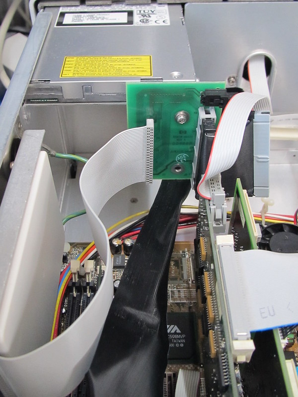
Windows 98 and the original software seem to work just fine with the converter PCB in the middle so this is the final setup:
BTW: this picture shows another problem I didn't spot until I made this picture!
USB sticks & Win98I still wanted to be able to use USB sticks to save screendumps and data to. Sure I could use the network for that but USB is easier. After some Googling I found this page
http://www.technical-assistance.co.uk/kb/usbmsd98.php which has a software package to install USB stick support on Win98. After installing I had to re-install the driver for the USB sticks I had inserted earlier but after that it worked just fine.
Leaky capacitors!This picture says it all:
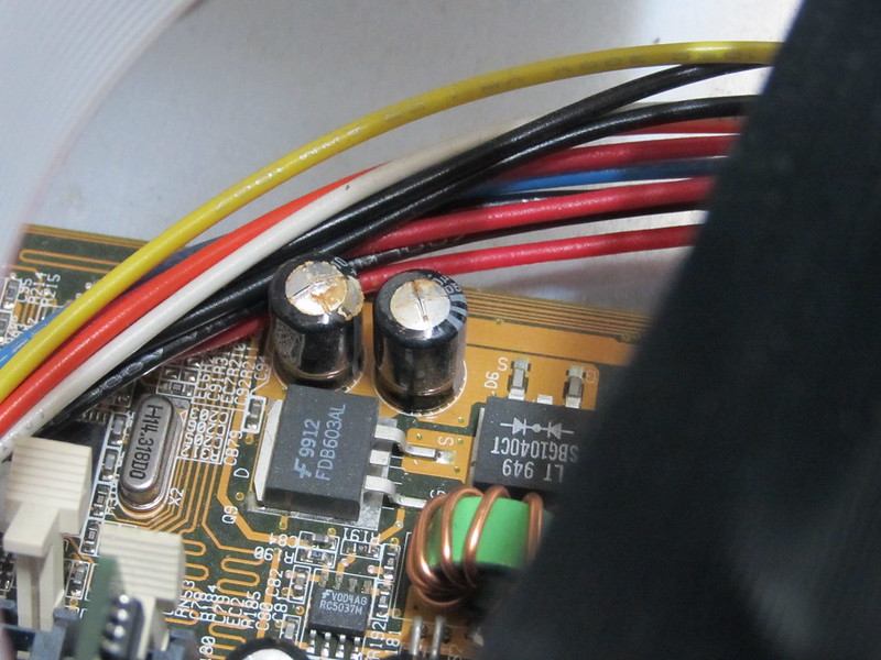
This meant I had to dissasemble the PC part and thus take all the boards and the motherboard out:
I had some new low ESR capacitors lying around and for good measure I added a 4.7uf 100V ceramic.
After putting everything together the scope still worked so I guess the capacitor replacement went OK.
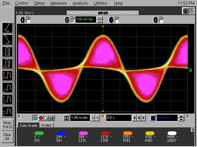
Time for some playLet's try a 200MHz AM modulated signal first:
Add some color grading in the mix:
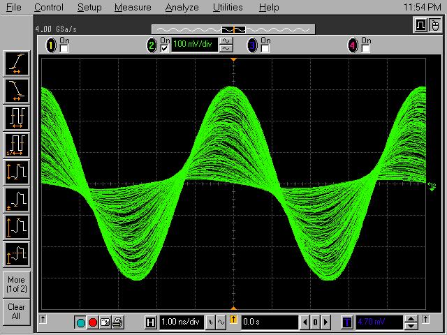
Let's try FFT and stacked math functions on a 200MHz FM modulated signal (+/-10MHz FM swing)
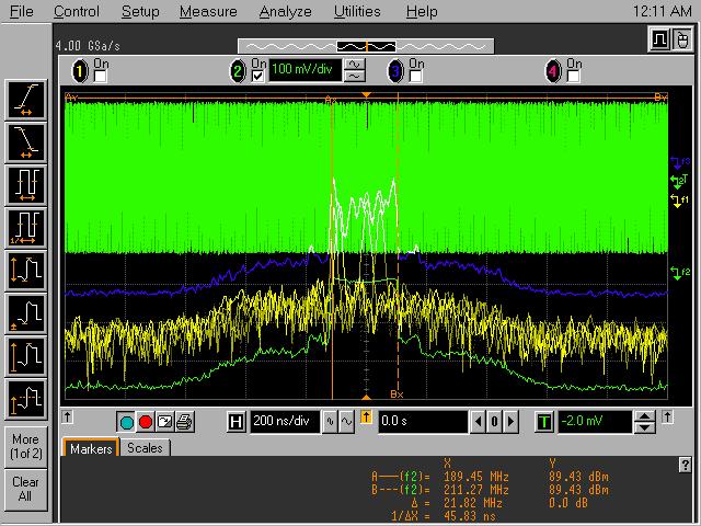
The yellow line is the base FFT trace. The green is the max hold and blue is the averaged FFT trace. I have not tried it but it should be possible to have more than one FFT trace.
I checked the risetime from a square wave. When the samplerate is 4Gs/s the (calculated) bandwidth is 1.1GHz. At 8Gs/s the bandwidth is 1.5GHz. Not bad!
What is left is to wait for the ADC hybrid to turn up and see which errors remain after I have fitted it. To be continued...


