I had been repairing Fluke 732a Voltage Reference that I purchased in "for parts or repair" state. This is a bit of a worklog/teardown, covering repair and 12v battery upgrade, for anyone who is interested. Click photos for high resolution versions (hosted by TiN).
It appears that sometime in the past the batteries in this Fluke 732a failed, leaked and caused some cascading failures. The unit came to me without batteries and with some parts of battery compartment missing.
After initial warm up:
10V read 10.00008 (8ppm out)
1.018V read 1.017998 (2ppm out)
1V read 1.000111 (
111ppm out!)
1V reading was off beyond what could be adjusted. Resistors responsible for division of 10V reference down to 1V are located inside of the oven. I attempted to partially disassemble the oven to look for 1V problem. I wanted to see if I can fix it, but half way though the disassembly things got complicated enough that I was not sure I would be able to assemble everything back the way it was. There is a lot is loose individual wires on the inside. The foam over last 30 years hardened and chances of me being able to put loose wires back into hardened foam were about zero.
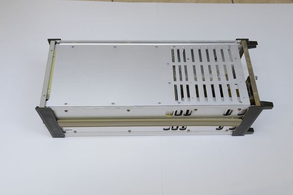
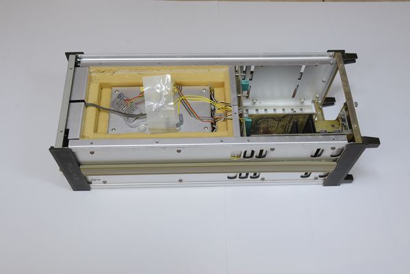
Here are some teardown photos. Top and bottom covers are off:
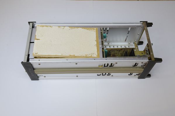
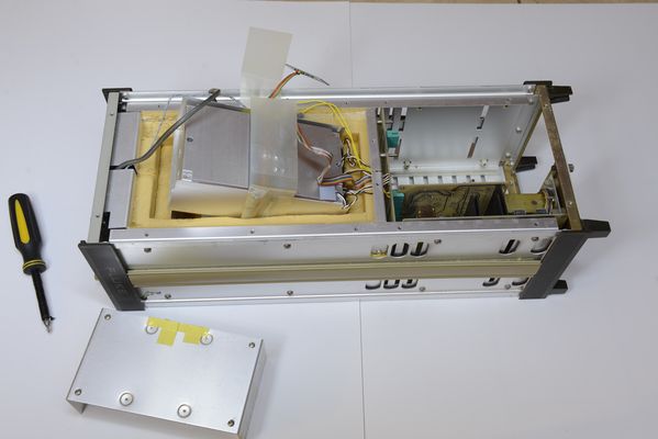
Top shield is off, revealing foam. The top piece of foam got fused with side foam making it very difficult to remove it without crashing. I used Stanley Blade to separate foam. Same blade was used (whole width of it) as pry bar of sorts to lift the top foam plank:
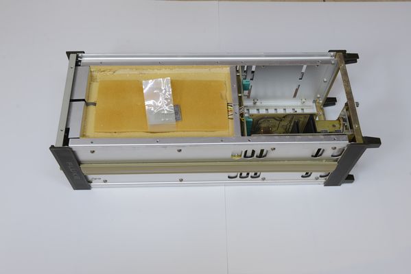
Inside you can see another layer of foam along with special card with links to adjust 10V reference in 5ppm steps. I switched the link to lower reading by 5ppm:
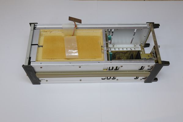
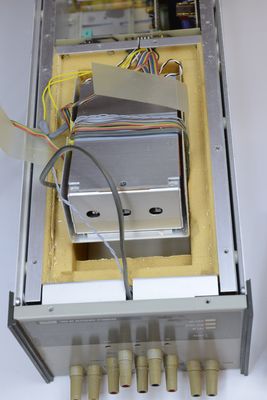
Underneath second foam plank there was an oven assembly:
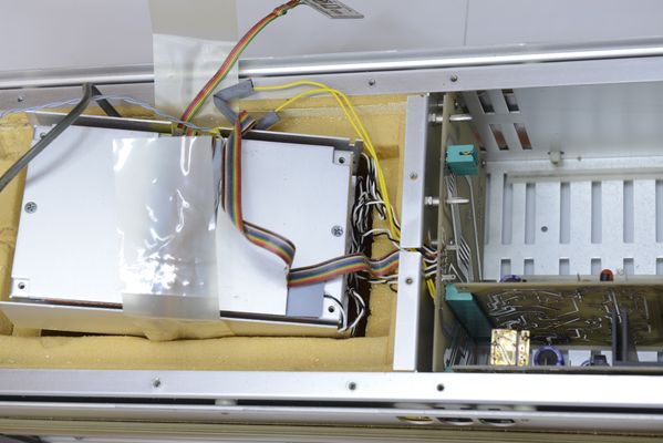
I removed its cover and pulled it out a bit:
At this moment I decided to stop and concentrate on the rest of the unit. After all if resistor/resistors responsible for 1V output had drifted by 111ppm in 30 years, there is no guarantee they stop drifting once I add additional adjustment network trying to bring 1V in range. By the way, it was actually very difficult to assemble the unit back from this point.
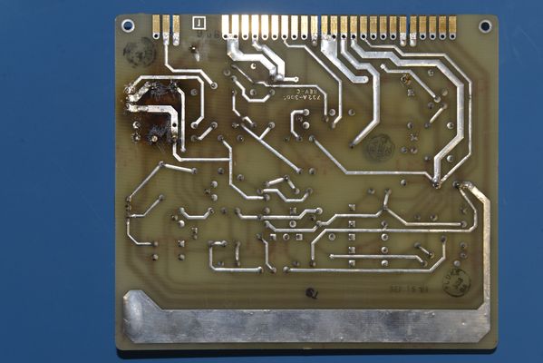
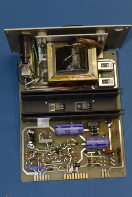
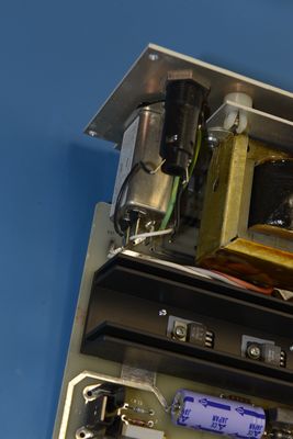
This is regulator PCB Assembly:
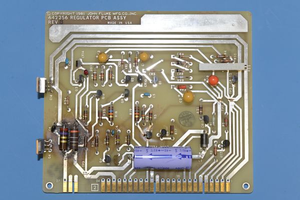
Note the charring underneath of two large resistors. I guess it was the failing battery that caused them to overheat. It appeared that resistors were replaced. I made sure they are working and also desoldered a small polystyrene cap next to them to check it. Cap was Ok. I cleaned up the worst of charring from the board. I could not remove all of the compromised material without totally destroying the PCB. The large electrolytic cap appeared physically lumpy and not even cylindrical. It was of cause replaced. One of two transistors on the bottom of this board had hardware missing that was designed to tie it to bottom shield for heat dissipation. I bough and replaced nylon non-conductive washers and corresponding screws. I kept old thermal sill pads. I hope that is OK.
Battery compartment was missing one metal panel on the side. Thankfully I have a small milling machine and I was able to make an aluminum cross plank that is now holding batteries in place and together:
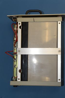
also decided to convert the unit to using two 12V batteries instead of four 6V batteries. I ordered two of: "EnerSys Genuine NP5-12 Genesis NP Series 12V 5Ah" from Amazon. They seem like the same brand and kind that Fluke is using, just much cheaper from Amazon. I fully charged and load tested both batteries @ 250mA and one was 2% less than nominal capacity and another 5% more. Close enough for me. Switching wires and connectors for using 2 batteries instead of four was completely trivial. Now terminal location for new batteries came out to be different than existing holes. Milling machine to the rescue again. Since I made new holes a bit smaller than old, I used kapton tape around them to prevent me from accidentally shoring the batteries while installing/removing them. See yellow insulation in photo:
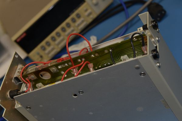
Two 12V battaries are a bit smaller than four 6V, so I had to create few spacers to keep batteries from rattling.
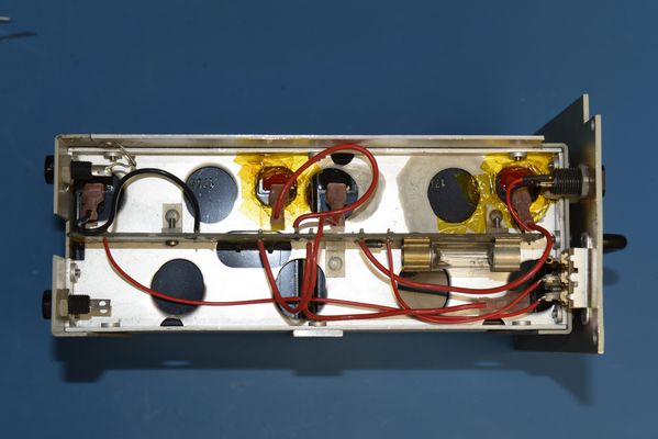
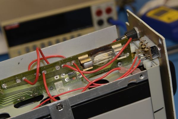
Battery compartment includes a small lamp that apparently is not used as a lamp, but as some sort of regulator.

The PCB next to the lamp showed discoloration, but lamp itself appeared ok when I removed and checked it:
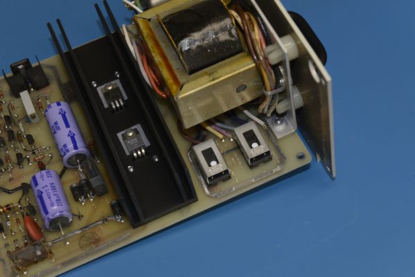
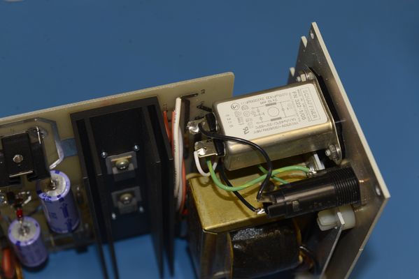
Power supply circuit appeared fine. I just changed two electrolytic capacitors and replaced Schaffner time delay bomb of an EMI filter, and replaced it by Delta 06GEEG3E. I hope it is sufficient:
Now Fluke 732a had been powered and running for few weeks. It would not stabilize for first two weeks, but now looks stable. I will be monitoring it for months to come and still want to do a study of thermal behavior of internal boards that appeared charred to make sure the problem is not continuing.
Is here is a member in a derivable distance from NJ with a calibrated Fluke 732 or something similar? I would really want to synchronize my 732 to theirs. Please let me know by a PM or something.
Questions, comments, and suggestions are welcome.


