Author Topic: Tarnished copper as a heat distribution plate in a reflow oven  (Read 5211 times)

0 Members and 1 Guest are viewing this topic.

Offline mjkuwpTopic starter

  • Supporter
  • ****
  • Posts: 259
  • Country: us
  • mechanical engineering defector
    • The Mz Lab
This is related to some other conversations about ovens and thermocouples, etc.  I am trying something new and thought it timely to share.

I wanted to use a copper sheet in my electric imp-controlled reflow oven but I assumed that the shiny surface would not receive the radiated energy very well.

To hep the heating I tarnished a copper sheet using a solution of Liver of Sulfur and distilled water at 60C.   I did a really quick and easy test and it seems to work well so far.

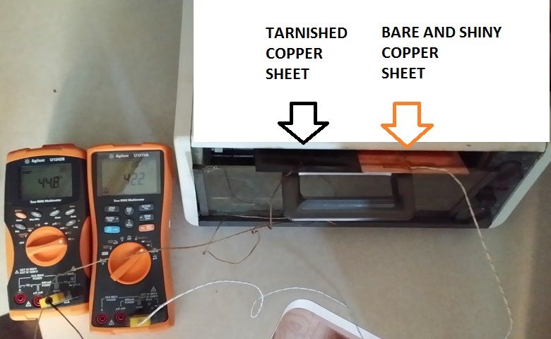
Thermocouples were taped to each sheet and I put them into my toaster oven (not my reflow oven but actually the one I use for toast every morning : )

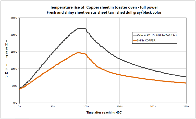
Somewhat interesting is that initially they appear to rise at the same temperature but starting around 40C the tarnished one really starts to take off.  The shiny copper one had an initial rise of 1.2C per second.  The tarnished one has an initial rise of 2.2C/sec.  To double-check I dipped a bit of paper towel in water and checked the sizzle.  The difference was quite remarkable so even if I have a bit of error from the thermocouple mounting I am sure the results are real enough.


This is a picture of the experiment setup.  The Agilent meters have Bluetooth modules on the back so I logged to the Android app. 


The next step is to do real reflow jobs with the tarnished plate.  On the down-side the radiation heat will not go directly to the bottom of the board as it used to.  It will now go to this plate and there will be a mixture of poor conduction and radiation to reach the bottom of the PCB.  Meanwhile the top of the board and all the components will be exposed to the top heating elements.


Overall the big goal here is to obtain 1. good soldering results, possible for multiple boards.  2. good temperature feedback that can be correlated to board temperature.
 

Offline tjb1

  • Regular Contributor
  • *
  • Posts: 146
  • Country: us
Re: Tarnished copper as a heat distribution plate in a reflow oven
« Reply #1 on: June 06, 2014, 05:56:09 pm »
I wonder if a grid of tarnished - shiny would act any differently.  You would have area to reflect and also to absorb and depending on the grid size you could adjust to your liking or normal board size.
 

Offline marshallh

  • Supporter
  • ****
  • Posts: 1462
  • Country: us
    • retroactive
Re: Tarnished copper as a heat distribution plate in a reflow oven
« Reply #2 on: June 06, 2014, 07:38:47 pm »
One of the best improvements that I don't see anybody doing: putting metal shielding over the elements to prevent direct line-of-sight heating. Matte black painted metal is all you need
Verilog tips
BGA soldering intro

11:37 <@ktemkin> c4757p: marshall has transcended communications media
11:37 <@ktemkin> He speaks protocols directly.
 

Offline mazurov

  • Frequent Contributor
  • **
  • Posts: 524
  • Country: us
Re: Tarnished copper as a heat distribution plate in a reflow oven
« Reply #3 on: June 06, 2014, 08:02:34 pm »
One of the best improvements that I don't see anybody doing: putting metal shielding over the elements to prevent direct line-of-sight heating. Matte black painted metal is all you need

I use fine stainless steel mesh to shield bottom pair of heaters.
With sufficient thrust, pigs fly just fine - RFC1925
 

Online M4trix

  • Frequent Contributor
  • **
  • Posts: 312
  • Country: hr
Re: Tarnished copper as a heat distribution plate in a reflow oven
« Reply #4 on: June 06, 2014, 08:13:29 pm »
Can two crumb trays be used as top and bottom shield? Anyone tried this?  :-//
 

Offline T3sl4co1l

  • Super Contributor
  • ***
  • Posts: 21972
  • Country: us
  • Expert, Analog Electronics, PCB Layout, EMC
    • Seven Transistor Labs
Re: Tarnished copper as a heat distribution plate in a reflow oven
« Reply #5 on: June 06, 2014, 11:04:57 pm »
Specifically, matte black "high temp" enamel, good to like, red hot or so :)

Tim
Seven Transistor Labs, LLC
Electronic design, from concept to prototype.
Bringing a project to life?  Send me a message!
 

Offline FrankenPC

  • Supporter
  • ****
  • Posts: 335
  • Country: us
Re: Tarnished copper as a heat distribution plate in a reflow oven
« Reply #6 on: June 07, 2014, 04:13:42 am »
Has anyone tried a convection toaster oven?  I wonder if the internal fan air flow evens out the heat distribution.
Chinglish poetry: In the hot summer. In the car ran full steam. It tastes strange. For this worry? With this fan will bring you a cool summer. Suitable for all kinds of cars. Agricultural vehicles. Van. Tricycle.
 

Offline marshallh

  • Supporter
  • ****
  • Posts: 1462
  • Country: us
    • retroactive
Re: Tarnished copper as a heat distribution plate in a reflow oven
« Reply #7 on: June 07, 2014, 04:01:45 pm »
Has anyone tried a convection toaster oven?  I wonder if the internal fan air flow evens out the heat distribution.

Actually the convection is critical for good reflow, and not having it will cause you all sorts of heat shadow and uneven problems.
Verilog tips
BGA soldering intro

11:37 <@ktemkin> c4757p: marshall has transcended communications media
11:37 <@ktemkin> He speaks protocols directly.
 

Offline philpem

  • Frequent Contributor
  • **
  • Posts: 335
  • Country: gb
  • That Sneaky British Bloke
Re: Tarnished copper as a heat distribution plate in a reflow oven
« Reply #8 on: June 07, 2014, 08:12:39 pm »
Has anyone tried a convection toaster oven?  I wonder if the internal fan air flow evens out the heat distribution.

Actually the convection is critical for good reflow, and not having it will cause you all sorts of heat shadow and uneven problems.

I'll second that. I had no end of trouble with my homebrew reflow oven until I fitted a cheap aftermarket oven fan to the right side. Now the heating is more even, the thermocouple tracks actual temperature and the boards don't end up burned :)

Only catch is that the exposed fan blade is a bit of an injury hazard... that was the smallest oven fan I could find :(
Phil / M0OFX -- Electronics/Software Engineer
"Why do I have a room full of test gear? Why, it saves on the heating bill!"
 

Offline mjkuwpTopic starter

  • Supporter
  • ****
  • Posts: 259
  • Country: us
  • mechanical engineering defector
    • The Mz Lab
Re: Tarnished copper as a heat distribution plate in a reflow oven
« Reply #9 on: June 08, 2014, 01:44:57 pm »
The oven that I started with has a convection fan and it also has perforated metal covers over each heating element.  It is only 40 USD.  My controller can control the fan but I think it is just fine to leave it running all the time.  The top and bottom elements have seperate control but since I have always needed full power I am not sure how much use this is.


before and after..


I did not use the crumb tray that came with the oven.  I think one could makes use of the tray if you are good with cutting and folding metal.

PS
little bit more detail about the tarnishing and the description and code for my electric imp oven project is here.
http://mjkuwp94.tumblr.com/tarnishing
 

Offline mjkuwpTopic starter

  • Supporter
  • ****
  • Posts: 259
  • Country: us
  • mechanical engineering defector
    • The Mz Lab
Re: Tarnished copper as a heat distribution plate in a reflow oven
« Reply #10 on: June 11, 2014, 01:55:00 am »
follow up.  I made three boards using this tarnished sheet. 

The setup:

feedback TC connected to a spare board, a smaller board next to the board being soldered

A second thermocouple on the copper plate was read with a DMM.

I did one board at a time - just sat it on the plate next to the scrap board with the TC on it.

I opened the door of the oven when the board sensor read 215C and the peak temperature was about 222C.

The results;


What I noticed is that when the elements were full on the copper was 10C to 15C hotter than the boards.  During soak the temperature difference was very small, just a couple C.

I watched the solder on the boards melt as the temp came up and hit printscreen on my PC.  The recorded temps were 183C, 184C and 185C.  This is uncannily spot-on to the melt temp of the solder (183C).

I wasn't watching closely but I guess the sensor on the copper plate was probably reading 200C at that point.

The thru-hole stuff was done immediately after I pulled the board out before it cooled down.


Share me

Digg  Facebook  SlashDot  Delicious  Technorati  Twitter  Google  Yahoo
Smf