The Uss pin contacts the chip carrier before it is connected with the Uss bonpad.
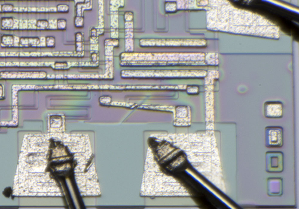
At the bondpad in the lower right corner there is a cutted wire. Whether this was done intentionally or the line was damaged during production cannot be said with certainty.
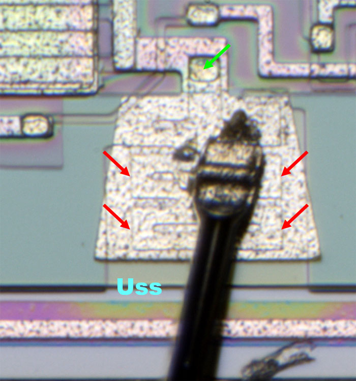
Underneath the bondpads you can spot a protective structure (red), which is contacted at the upper end of the bondpad (green). The whole structure represents a MOSFET with a thick gate oxide. When a problematic voltage pulse occurs, the structure becomes conductive, connecting the bondpad to the Uss potential and thus draining the pulse.
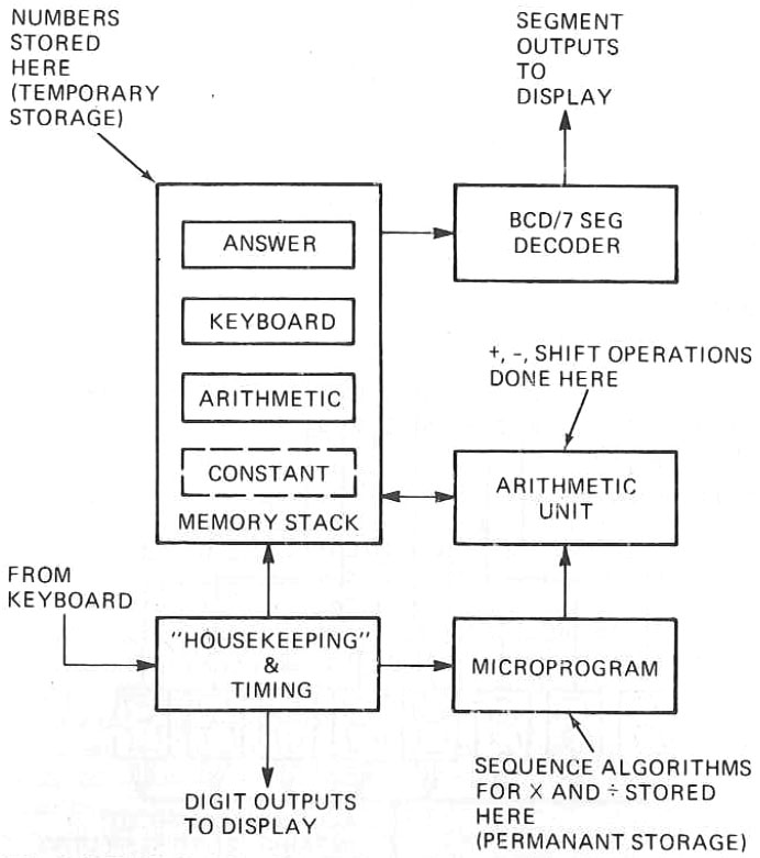
In the magazine "Radio Electronics" July 1974 there is a block diagram showing how a pocket calculator of this generation is constructed. The core of the microcontroller is the ALU which can perform addition, subtraction and shift operations. More complex calculations such as multiplications and divisions must be broken down to these operations.
A ROM contains the code necessary to control the system. A RAM provides the memory necessary to store the currently entered numbers, a constant, an intermediate result, and the end result.
The data is output via a BCD/7-segment decoder.
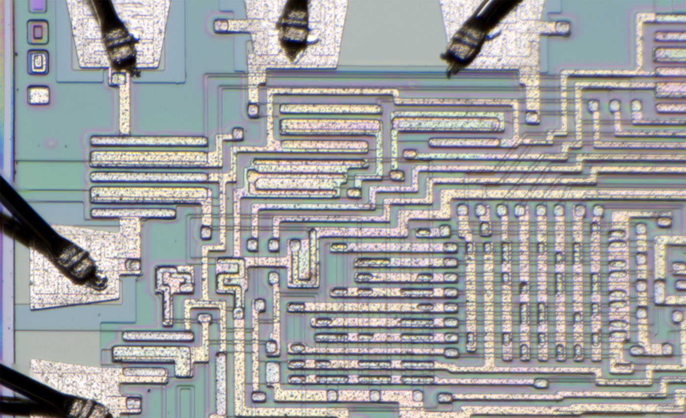
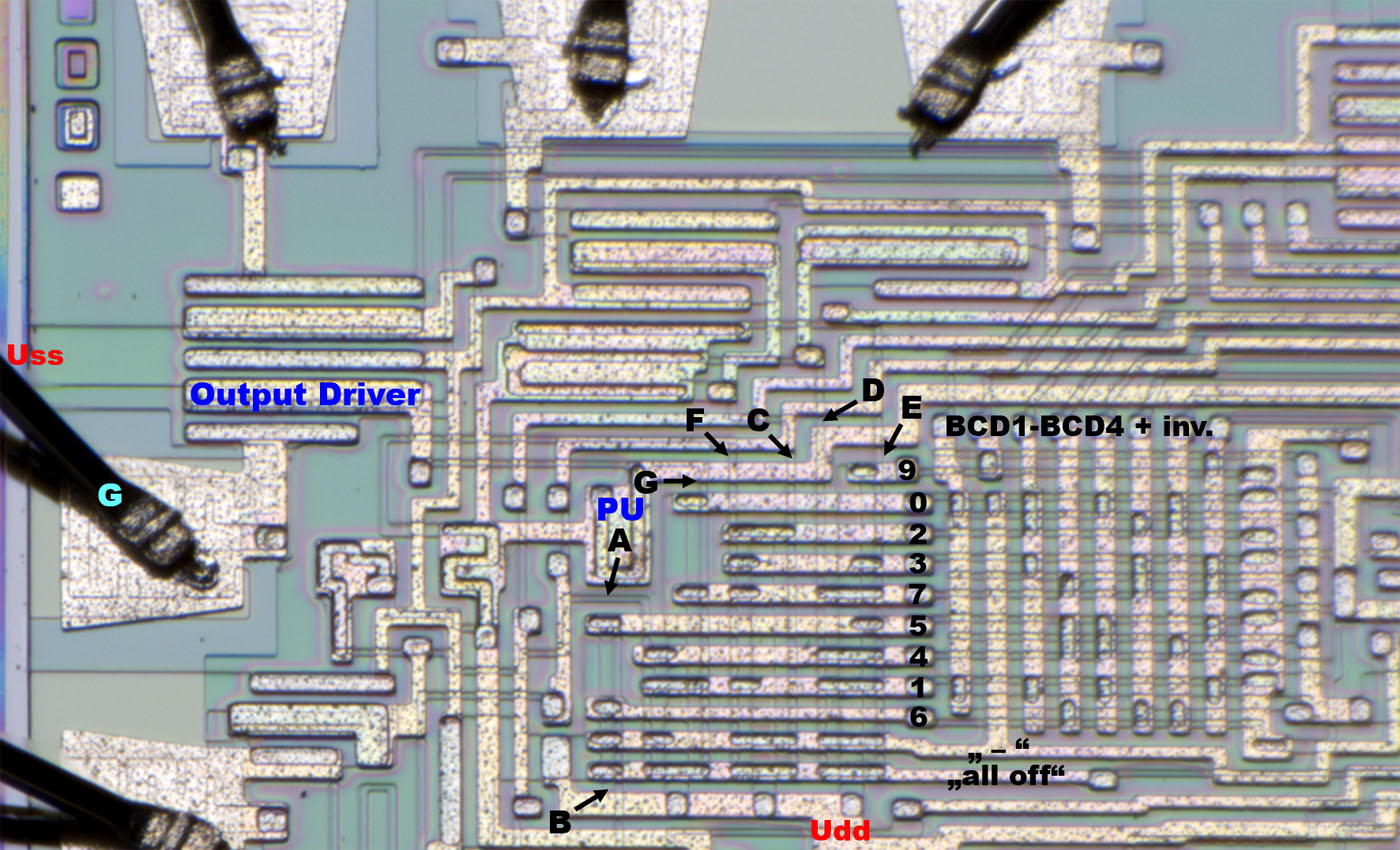
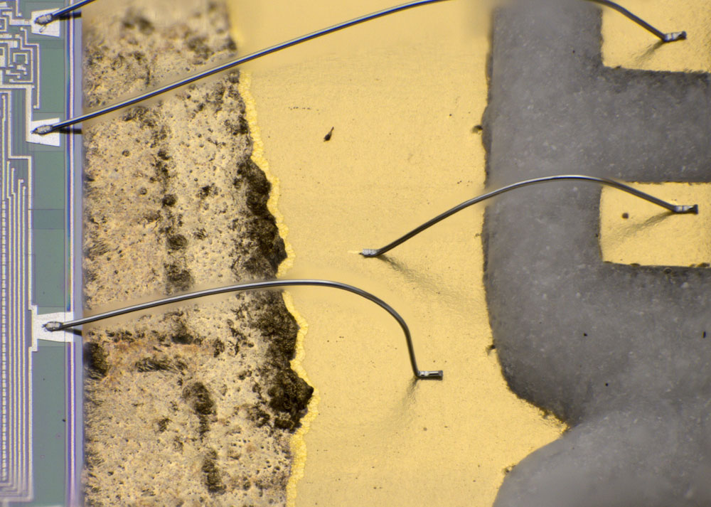
One part of the circuit that can be analyzed very well is the BCD/7-segment decoder. It consists of two blocks. The right block is differentially fed with the four BCD signals. In the matrix the distribution of the gate oxide areas ensures that one of the horizontally running lines becomes active depending on the BCD signals. Each line represents a number.
In the left block, the gate oxide areas are distributed in the horizontally running conductors in such a way that each of the numbers activates the appropriate segments of the display (A-G).
Each segment control line is connected to a pull-up structure and to a output driver. Some drivers are connected to Uss by connecting the frame structure.
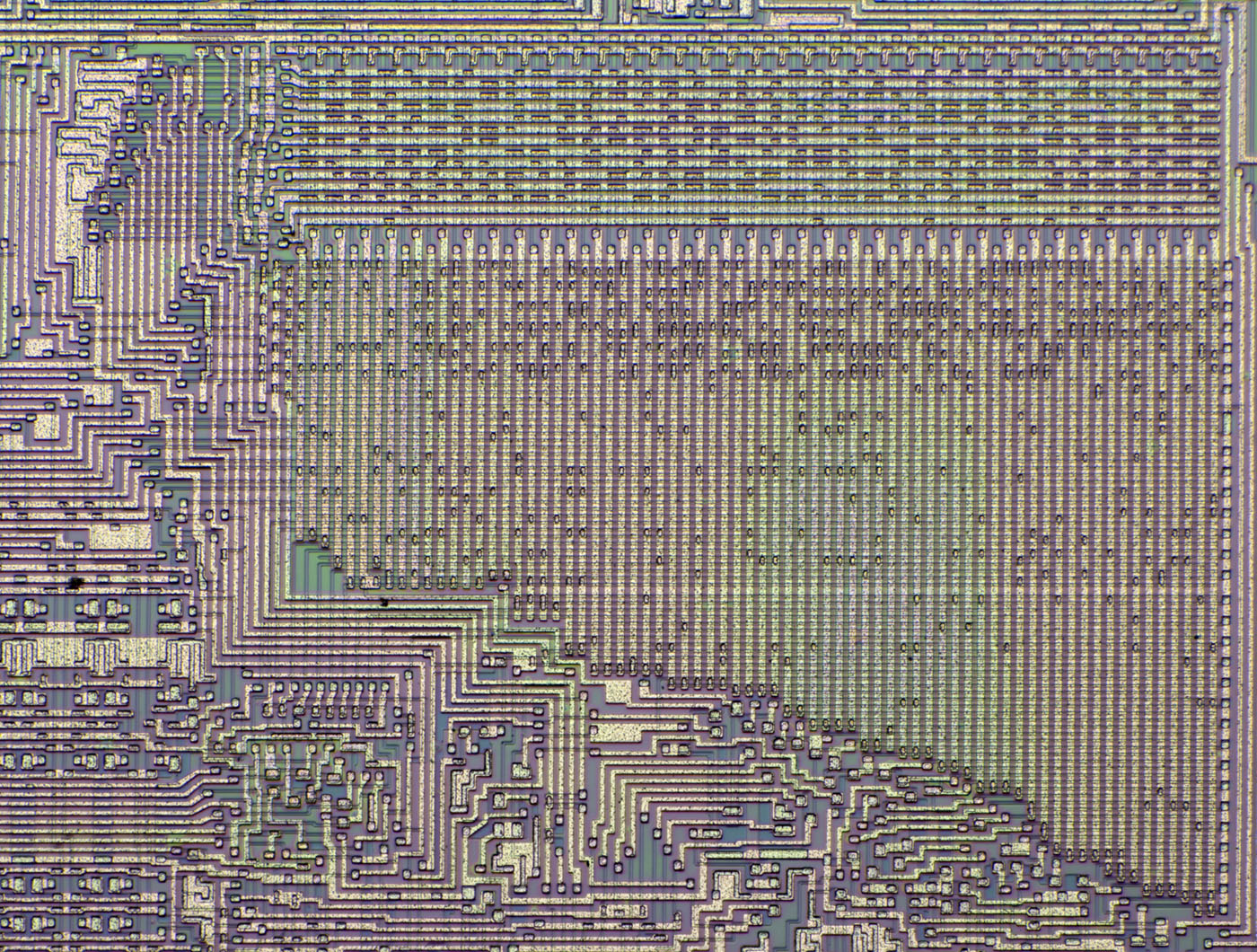
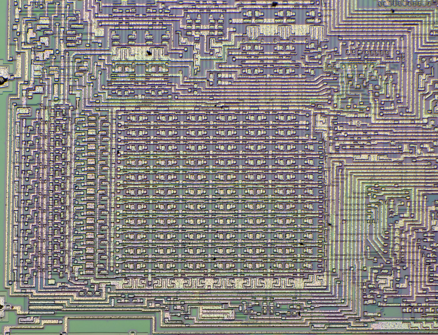
In the upper right area of the die is the ROM, which contains the control logic and takes up a lot of area. It is noticeable that the memory is not a square.
The upper area contains the column selection, which activates one out of 72 columns. On the side the rows output the necessary control signals. The upper rows seem to be partially coupled back to the column selection.
The distribution of the gate oxide areas represents the programm logic.
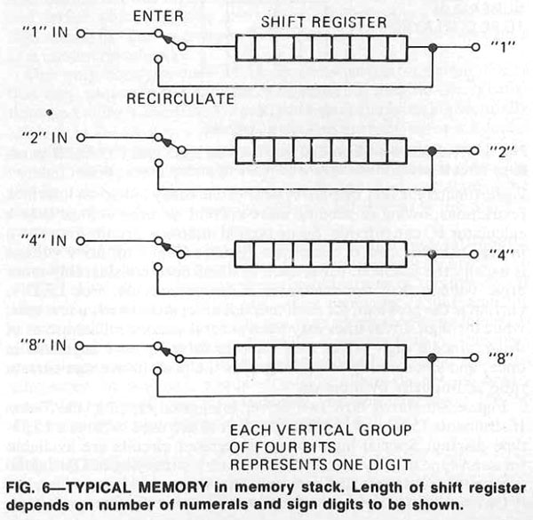
The already mentioned magazine "Radio Electronics" July 1974 shows the typical structure of the RAM in such a calculator. According to this, there are usually four shift registers which hold the four BCD signals. Each column in these four shift registers represents one digit. In addition, there are places for additional information such as sign and overflow.
The data passes through the shift registers continuously. This is necessary because it is usually DRAM that must be updated cyclically so that the information doesn´t degrade.
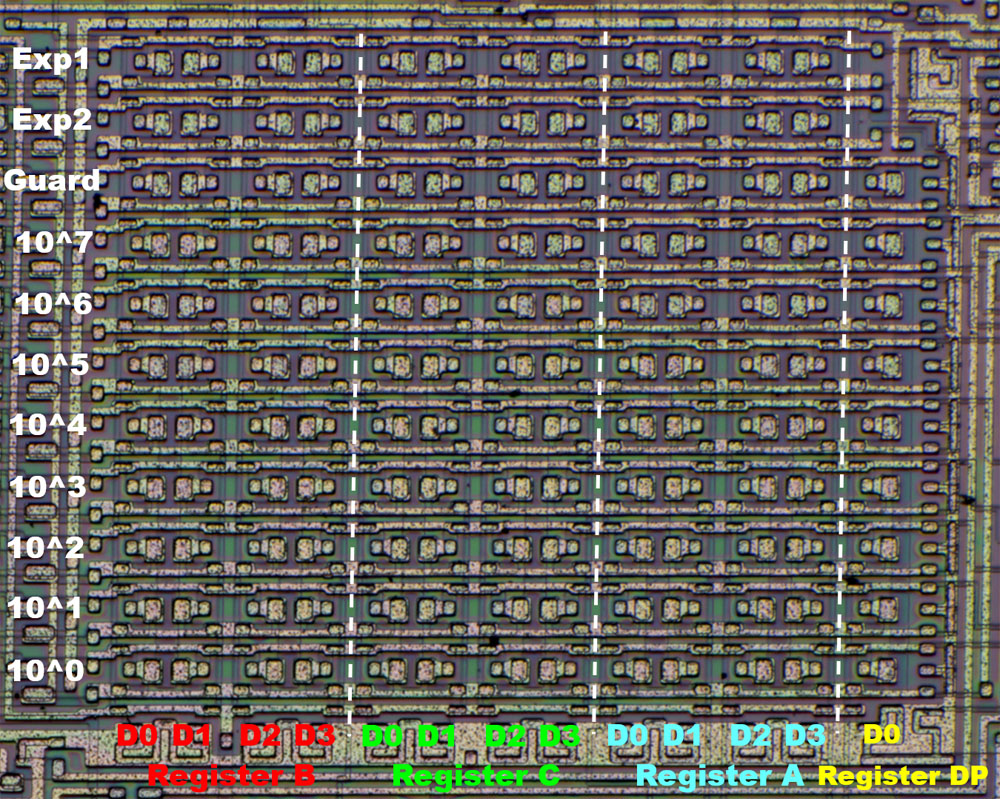
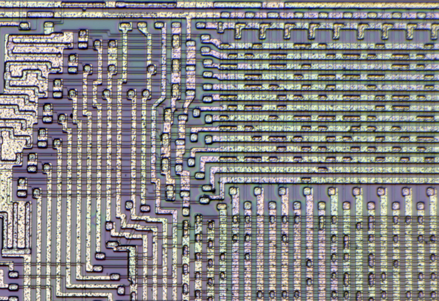
The RAM memory has 11 lines. In addition to the 8 digits of the display, there are consequently 2 bits left for sign and overflow. One bit must remain free so that the information can rotate in the shift register without additional intermediate memory.
The columns probably represent 3 groups of 4, representing 3 BCD numbers. We can assume that these are the memory areas for the current input, the subtotal and the result.
On the far right, there remains just one column with 9 individual memory cells. There the optional constant must be stored.

The constant can only be used for multiplications and divisions. These operations are performed differently than additions and subtractions. Probably that is why they are stored as binary numbers. In addition, the possible number range does not have to be very large.
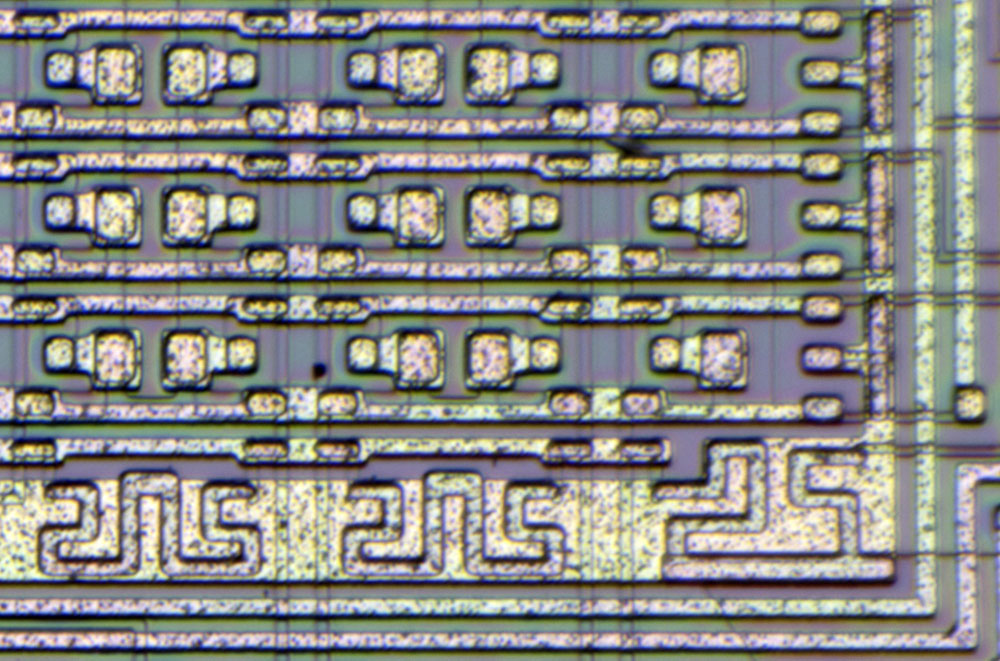
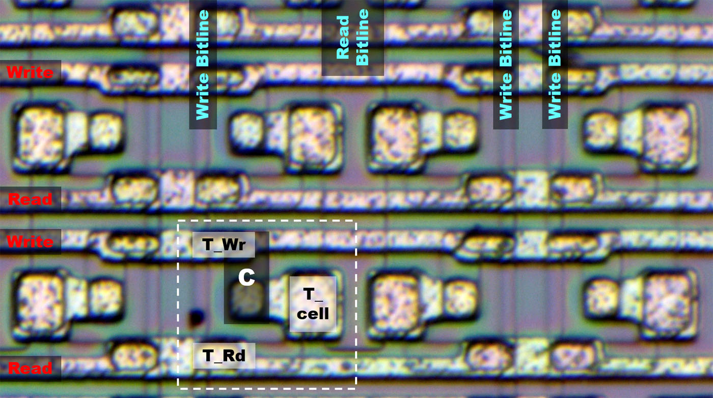
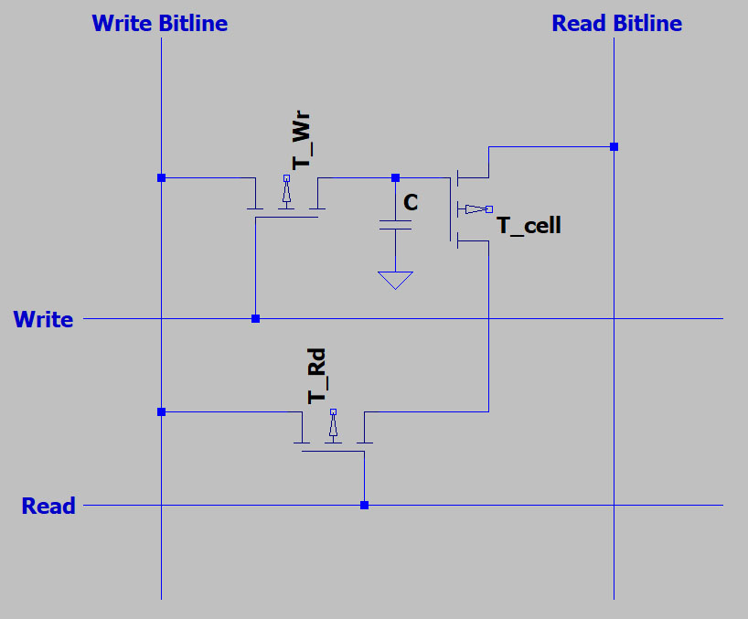
The individual memory cells are 3T1C cells, which are constructed with three transistors and a capacitor. The capacitor is just a slightly wider line in the silicon. It controls the transistor T_cell. In contrast to a 1T1C RAM like the U2164 (
https://www.richis-lab.de/RAM02.htm), a 3T1C RAM has the advantage that a read operation does not erase the memory contents.
When configured as a shift register, the 3T1C configuration has another advantage. For the function as a memory it would be sufficient to connect the transistor T_Rd to Udd. Instead, the transistor is connected to the write bitline. Since the read out signal is low impediance in contrast to a 1T1C RAM, it can be fed directly into the next cell. Thus, one cycle is sufficient to transfer information from cell to cell.
https://www.richis-lab.de/calc02.htm 


