Author Topic: circuit for detecting a 220v AC signal  (Read 2974 times)

0 Members and 1 Guest are viewing this topic.

Offline drakejestTopic starter

  • Regular Contributor
  • *
  • Posts: 200
  • Country: 00
circuit for detecting a 220v AC signal
« on: September 11, 2021, 02:04:07 pm »
I would like to create a circuit that detects if there is 220v AC present on the inputs

The requirements i set out to achieve are:
  • Must be able to detect 220v AC that is switched less or equal to 5Hz
  • Must be robust and safe for the electronics on the other side, so can withstand surges and other factors typical mains voltage is subjected to.
  • Outputs are already filtered out meaning 3.3v DC for 220v is present and  0v DC if there is none, not a square wave looking signal for "on"

Looking through circuits online i found this module


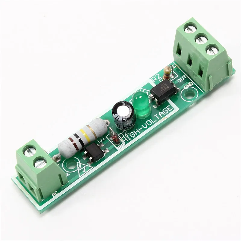
It has an optocoupler which provides isolation which i think is good, but i do not like that its using an electrolytic capacitor which is very prone to failure especially in 220v AC setting when surges are not uncommon.


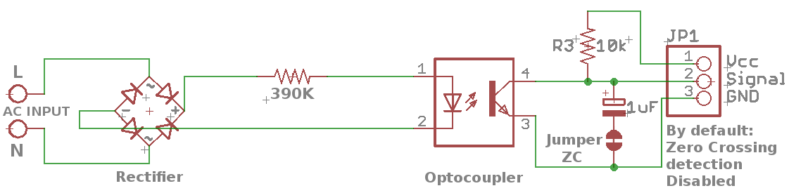
another circuit which i think i like better since it does not use an electrolytic, I think i would need to add a MOV to protect from surges and there are cheap full bridge rectifier like the MB10s

Can anybody suggest an improvement to the circuit or a better type of circuit. I think a good place to imitate a circuit are those used in industrial applications as they have stricter requirements does anybody know how its done there?
 

Offline jmelson

  • Super Contributor
  • ***
  • Posts: 2800
  • Country: us
Re: circuit for detecting a 220v AC signal
« Reply #1 on: September 11, 2021, 11:09:08 pm »
Your 390 K resistor will only supply 0.8 mA to the LED, is that enough to turn it on?
I'd use two (or more) SMT resistors in series, so the voltage across each is reduced.  Also, keep them away from the mounting screws.
The 390K resistor will only dissipate about 1/4 W PEAK, average should be much less.
Jon
 

Offline james_s

  • Super Contributor
  • ***
  • Posts: 21611
  • Country: us
Re: circuit for detecting a 220v AC signal
« Reply #2 on: September 11, 2021, 11:12:52 pm »
Either of those circuits looks like it would work fine, you could replace the capacitor with a higher quality part if you are worried about that. You could also make your own opto coupler using a 220V neon indicator and a phototransistor.
 

Offline floobydust

  • Super Contributor
  • ***
  • Posts: 7299
  • Country: ca
Re: circuit for detecting a 220v AC signal
« Reply #3 on: September 11, 2021, 11:20:50 pm »
For industrial applications, a problem can be the minimum voltage threshold. If you have 80VAC do you want the circuit working? People add a series zener or resistor across the LED to shift this. PLC's will add a two transistor constant-current source.
I use sensitive 1mA opto-couplers i.e. MOCD217 to keep heat down. The resistor comes first, acting as a fuse. Otherwise, a shorted bridge causes smoke.

Another zero-cross (only) circuit discussed here: https://www.eevblog.com/forum/projects/mains-zero-crossing-detection/msg3469950/#msg3469950
 

Offline DeanA

  • Regular Contributor
  • *
  • Posts: 116
  • Country: au
    • Design Electronics
Re: circuit for detecting a 220v AC signal
« Reply #4 on: September 12, 2021, 12:34:03 am »
There is:
MID400: AC Line Monitor Logic Output Optocoupler
Which I have used successfully in a commercial application for 230VAC.
https://www.onsemi.com/products/interfaces/high-performance-optocouplers/specific-function-optocouplers/mid400


Share me

Digg  Facebook  SlashDot  Delicious  Technorati  Twitter  Google  Yahoo
Smf