Author Topic: Avionics reverse-engineering: F-4 Voice Warning Generator  (Read 1725 times)

0 Members and 1 Guest are viewing this topic.

Offline D StraneyTopic starter

  • Regular Contributor
  • *
  • Posts: 233
  • Country: us
Avionics reverse-engineering: F-4 Voice Warning Generator
« on: June 15, 2024, 01:15:08 am »
I already took a quick look inside this one (here and 
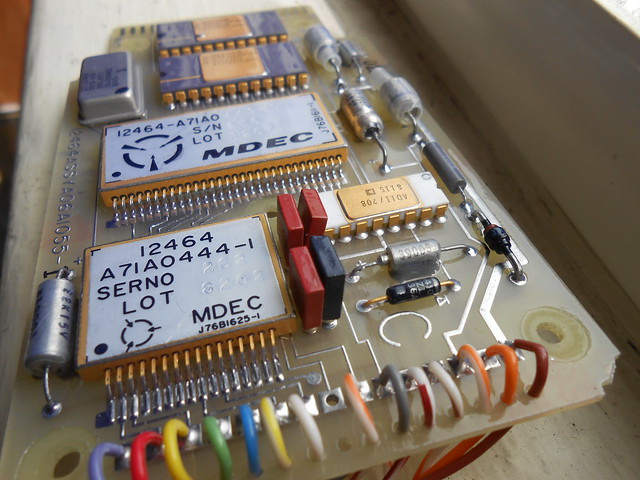
here) but there was enough reverse-engineering to be done here that I figured it deserved a topic of its own.  The story so far is that this device from 1982 generates the audio signal for warning messages in an F-4 fighter jet.  I wasn't sure at first if it would have a miniaturized tape player inside, but it does this using a single small board with two 8K x 8 PROM chips (containing sampled audio data), one mystery Analog Devices DAC chip, and two hybrids (one large, one small) which I cut open.


With the help of a local hackerspace's microscope (thanks to the Artisans Asylum open electronics nights!), I managed to ID all the IC dies, and trace out the circuitry inside each hybrid with a combo of the high-zoom photos and a lot of continuity checking with sewing needles.  The small hybrid handles interfacing from the outside world, with a lot of clamp diodes and series resistors to protect logic gate inputs from over-voltages in the "wild west" of aircraft wiring.  The large hybrid handles the actual logic of sequencing playback of audio samples.


Here's the schematics, also attached below as PDFs for easier viewing:


Ok, so, what's going on here and how does it work?

Clocks
The silver metal can on the board is a 16 kHz oscillator, which feeds the large hybrid.  In the top-left corner of the large hybrid's schematic, you can see where it gets divided in half to produce 8 kHz, and then combined in a second flip-flop (U7B) to produce a 90-degree-delayed copy of the 8 kHz clock, to sequence the memory accesses properly.

Clocks at different stages can be gated by external pins, which have pull-up resistors and are connected externally only to the bare-pad testpoints that extend in a row down one side of the board.  These testpoints are probably used either for production testing finished units and/or for troubleshooting in the field.  An external tester probably uses an edge connector which mates with these rows of testpoints.

One of the 8 kHz clocks is fed to a CD4020 14-bit counter, where the frequency is divided further and further down for other purposes.  16 Hz is broken out to an external pin and sent only to a testpoint, but 8 Hz and 2 Hz are used internally for input & reset timing as we'll discuss next.

Input stages
5 different wires come straight into the small hybrid, where each input has a series resistor, clamping diodes, a pull-down resistor, and a filter capacitor (external film caps for some channels, internal ones for others).  These inputs all go to logic gate inputs, which we'll look at in a minute.  One wire (gray) just goes to a resistor to ground, which might be some sort of external ID or "module present" indication.  The small hybrid also contains the voltage divider resistors that set output voltage for the LM117 that generates the +5V supply, mounted off-board on a metal plate.

The red wire and a "ready" signal from the large hybrid get combined and used to gate 3 of the input signals (blue, green, & yellow wires).  When either the red wire is low or the "ready" input from the large hybrid is low, the 4011 output (pin 11) is high and all the "received" blue/green/yellow logic outputs are forced high.  This essentially disables them, as these signals drive edge-triggered logic within the large hybrid - so the red wire seems to be an "enable" input.

Once these signals go inside the large hybrid, they're de-bounced and short pulses are eliminated by a series of CD4015 shift registers, using an interesting scheme.  A low input resets the shift register, while a high input allows a '1' to be clocked further and further down the shift register by the 8 Hz clock.  This means that the shift register outputs here only go high (and trigger other downstream circuitry) once the input has been high continuously for a significant fraction of a second.  This prevents false-positive triggers from stray pulses, such as EMI-induced voltage spikes in the external wiring.

Power-on reset
One of the channels in the small hybrid is not connected to an external input, but to an RC circuit charged from +5V.  This provides a "power-on reset" signal to the large hybrid, where the output (small hybrid pin 22) only goes low after the capacitor (an external film cap on the board) has had enough time to charge.  The PNP transistor provides the power-down handling: as soon as the +5V supply dips below the capacitor voltage, the PNP works as an emitter-follower and discharges the capacitor to follow the supply voltage.

The large hybrid dedicates one half of a CD4015 shift register to generating an even slower reset signal, triggered by the small hybrid's "reset" signal and clocked by a 1 Hz clock (derived by dividing the 2 Hz clock from the CD4020 even further).  This slower "reset done" signal is what's fed back to the small hybrid, and gates the external inputs via the NAND gates.

DAC & audio output
The mystery white-ceramic DIP package is a DAC of some kind, with an 8-bit resolution.  It gets its data from the PROMs via the large hybrid, and uses a slightly weird op-amp circuit inside the small hybrid to generate an audio output, which is AC-coupled and then exported on the purple wire.  There's some weirdness going on in the op-amp circuit & DAC, and I'm not sure what pins 1 and 16 are for on the DAC (pin 1 seems like an output, pin 16 might be feedback to an internal "auxiliary" op-amp?).

It might be a current output from the DAC that gets AC-coupled through the tantalum cap, and then converted to a voltage by the op-amp set up in a transimpedance (I to V) configuration.  The small ceramic feedback cap then would provide bandwidth limiting(/stability): it's a weird choice of place to connect that ceramic cap to the current output rather than to the op-amp's inverting input directly, but maybe that made the routing possible inside the hybrid.  I'm not sure what the 97Ω resistor to ground is for, then, as it only limits gain.  I have no idea then what pin 16 of the DAC would be doing.  A voltage output from the DAC would make even less sense though, as its output is fed directly to the op-amp's inverting input.

Either way, there's no non-linear components in here, unless the op-amp is something non-standard and weird - so if there's any audio data compression via log/exponential transfer functions (volume compression), it would have to be happening within the DAC itself.

Audio data readout
The audio samples are stored in two Signetics MKB36000-series PROM chips, each with a slightly different part number (which is probably a custom part number related to the contents).  These are each 8K x 8 bits.  The address and data lines of both PROMs are ganged together, and so only one is accessed at a time, determined by which ~CE (active-low Chip Enable) pin is active.  From this, it seems like there's only two separate audio samples, one per chip: this is backed up by the National Stock Number data for this voice warning generator:
Code: [Select]
NSN 6340-01-118-5999

A complete electrical warning unit specifically designed to provide an aural message/warning through pilot's earphones and/or visual message on pilot's heads-up visor display or a control panel indicating an unsafe aircraft attitude, such as: altitude, fire, canopy, pressurization, engine and/or rotor RPMs, etc. Item does not provide facilities for bells, buzzers, horns, sirens and/or lights. Excludes ALARM SET, PERSONNEL HAZARD.
...
SPECIAL FEATURES VOICE WARNING GENERATOR PROVIDES VOICE WARNING TO THE PILOT WHEN ALTITUDE IS TOO LOW AND WHEN THE CANOPY IS NOT SECURED
III FSC APPLICATION DATA AIRCRAFT ALARM,SIGNAL SYSTEMS
MANUFACTURERS CODE 12464
DESIGN CONTROL REFERENCE A05A0241
Because the CD4040 address counter is clocked by the 8 kHz clock, this shows the audio is sampled at 8 ksps, and each audio clip is about 1 second long.

In the top-right corner of the large hybrid schematic is a counter, connected to the PROM address pins, and an 8-bit latch between the PROM output data and the DAC input.  When there's a rising edge on the white wire or the blue & green wires, this latches the output of U2A high, and through a chain of OR gates, brings the "Playback" signal high.  The high "Playback" signal allows the address counter to cycle through the PROM's entire address space; at the same time, it also enables the 8-bit data latch (built out of a CD40174 and a CD4013) which latches the previous PROM data output for the DAC.

When the address counter reaches the end of the address space and rolls over, the highest bit goes low, and so this creates a rising edge via U4A's ~Q output to create a "Playback Done" signal.  This "Playback Done" is used to reset U2A and essentially turn off playback mode when the sample is done playing.

The "Playback in progress" signal is sent to a mystery chip in the large hybrid, which has what looks like a couple large power transistors.

The probable-output from this mystery power-driver chip is then sent out through pin 58, and to the white/brown wire to the external connector (protected by a TVS diode).  This seems to be a "audio playback in progress" output signal to some external equipment and/or for troubleshooting, maybe to avoid trying to trigger a playback while one is already in progress.

Sample selection
The yellow wire seems to select which audio sample to play.  A rising edge on the yellow wire sets U3B's output high, and from there a strange series of events happens with U3A and U2B, but as far as I can tell it seems to end with U13C's output being a "sample select" signal.  This "sample select" is fed both inverted and non-inverted to two large AND gates, each of which drives one of the PROM Chip Enable signals, to select between the two PROMs.  Because the MKB36000 PROM uses an edge-triggered I/O scheme, where read operations are started by a falling edge on Chip Enable, the 8 kHz clock is one of the inputs to both AND gates so that the selected Chip Enable signal is re-asserted every clock cycle.

The logic around the playback sequencing and the yellow wire is pretty twisted and I haven't worked through it in detail, so I'm not entirely sure what's going on there...
...but it looks like in the D-flip-flop-spaghetti there might be accommodations for the yellow wire going high while a sample is already playing, and triggering a playback of the second sample once the first has finished playing.  That's my surface-level read on what U3A/U14C/U2B are doing.

Making it work
So of course, the goal is to get it to play back the stored audio!  I powered up the board first with 9V, then with 24V (as 28VDC is a standard aircraft requirement): it drew a few mA, and the +5V power supply was accurate.  I tried pulling the red wire to +5V while pulsing various combinations of the white and yellow wires while watching the purple audio output on my scope, but couldn't get any response out of it.  Unfortunately, when I tried to carefully probe inside the large hybrid to see if the 16 kHz clock was active, my hand slipped - the scope probe's ground ring slipped and touched something, and now it won't turn on anymore without excessive current draw.  On a bench prototype I'd usually be soldering wires and loops everywhere to prevent exactly this kind of thing from happening, but it's all covered with conformal coating here (and I want to disturb it as little as possible, outside of removing the hybrid lids).

Since it seems like I've fried something inside the large hybrid, the next backup option is to read out the memory data directly.  I can cut the large hybrid's bond wires for the external pins that lead to the PROMs (and the +5V pin, so it doesn't drag down the board's 5V power), and connect a bunch of little test clips to the large hybrid's PROM pins on the inside, then use my trusty Batronix programmer to read the PROM data as long as a similar-enough model is supported.  It's more of a pain, but such is the price of shaky hands I guess.
« Last Edit: June 15, 2024, 01:16:54 am by D Straney »
 
The following users thanked this post: SeanB, boB, daqq, xrunner, RoGeorge, ch_scr

Offline moffy

  • Super Contributor
  • ***
  • Posts: 2020
  • Country: au
Re: Avionics reverse-engineering: F-4 Voice Warning Generator
« Reply #1 on: June 15, 2024, 04:37:21 am »
It's cool what can be accomplished with limited resources, 2 by 8k PROMs and an 8 bit DAC and you have a multi message annunciator. :)
 

Offline D StraneyTopic starter

  • Regular Contributor
  • *
  • Posts: 233
  • Country: us
Re: Avionics reverse-engineering: F-4 Voice Warning Generator
« Reply #2 on: June 19, 2024, 03:09:44 am »
Yeah, I enjoyed the simple sequencing logic of just "use a D-FF that gets cleared when a counter rolls over".  The 2 messages is much less impressive than I'd initially expected; thought it would be something like the Sperry VA-100 Voice Advisor which has 24 different phrases that get combined together to announce numbers, for example.  ...or a different civilian McDonnell Douglas audio warning generator (captured by the same person).

I'd assumed, with more messages, that it would need compression of some kind to reduce bit depth - either non-linear compression of the signal range or doing some kind of "offset from previous value" scheme.  But getting a full 64Kb ROM per 1-second sample is comparatively easy.  It seems like 8 ksps sampling with 8-bit depth is actually some kind of standard for voice & telephony; this fits with the analog phone system (POTS) design bandwidth of 300 Hz to 3.4(-ish) kHz for good-enough voice transmission.

Also, for anyone else who happens to get one of these (seller might've been open to offers? was a while ago but I don't normally pay >$40 for old avionics), here's how the wire colors from my schematic translate to the external connector pin numbers, so you can try activating it yourself from the outside:
  • Brown = 1
  • Red = 2
  • Orange = 3
  • Yellow = 4
  • Green = 5
  • Blue = 6
  • Black = 7
  • Purple = 8
  • Gray = 9
  • Black = 10
  • White = 11
  • White/brown = 12
  • Black = 13
(I think all the black wires connected to various enclosure parts, from what I remember)
 
The following users thanked this post: moffy

Offline moffy

  • Super Contributor
  • ***
  • Posts: 2020
  • Country: au
Re: Avionics reverse-engineering: F-4 Voice Warning Generator
« Reply #3 on: June 19, 2024, 04:56:32 am »

I'd assumed, with more messages, that it would need compression of some kind to reduce bit depth - either non-linear compression of the signal range or doing some kind of "offset from previous value" scheme.  But getting a full 64Kb ROM per 1-second sample is comparatively easy.  It seems like 8 ksps sampling with 8-bit depth is actually some kind of standard for voice & telephony; this fits with the analog phone system (POTS) design bandwidth of 300 Hz to 3.4(-ish) kHz for good-enough voice transmission.

I looked into that a number of years ago, ADPCM or Adaptive Differential Pulse Code Modulation, basically you just encode the difference between the previous sample and the current sample, gives much better resolution for lower bit depths, but you have to use something like an integrator to sum all the previous samples.

P.S. This looks to be more like just DPCM.
« Last Edit: June 19, 2024, 05:21:22 am by moffy »
 

Offline bdunham7

  • Super Contributor
  • ***
  • Posts: 7994
  • Country: us
Re: Avionics reverse-engineering: F-4 Voice Warning Generator
« Reply #4 on: June 19, 2024, 05:07:58 am »
F-4?  Those were gone by 1982.  Are you sure that isn't from an F-18?  Can you play the voice commands and if so, do they sound like "Bitchin Betty"?

A 3.5 digit 4.5 digit 5 digit 5.5 digit 6.5 digit 7.5 digit DMM is good enough for most people.
 
The following users thanked this post: boB

Offline Bud

  • Super Contributor
  • ***
  • Posts: 7050
  • Country: ca
Re: Avionics reverse-engineering: F-4 Voice Warning Generator
« Reply #5 on: June 19, 2024, 05:12:21 am »
That is one pretty annoying voice, but maybe that was the point.
Facebook-free life and Rigol-free shack.
 

Offline eutectique

  • Frequent Contributor
  • **
  • Posts: 431
  • Country: be
Re: Avionics reverse-engineering: F-4 Voice Warning Generator
« Reply #6 on: June 19, 2024, 10:26:56 am »
That is one pretty annoying voice, but maybe that was the point.

That's playing on male instincts.
 

Offline D StraneyTopic starter

  • Regular Contributor
  • *
  • Posts: 233
  • Country: us
Re: Avionics reverse-engineering: F-4 Voice Warning Generator
« Reply #7 on: June 19, 2024, 03:16:13 pm »
Huh that's interesting!  Definitely a very "older family member you need to obey" voice, good for getting a quick reaction when you need it.

This one's definitely from the F-4: scroll down in a copy of the NSN record and there's "Materiel Management Aggregation Code   BF   SU:F-4 (PHANTOM II)".  According to Wikipedia at least it was in service until '96 in the US and longer in other places, so timeline is reasonable as one of the many common mid-life upgrades.

Online wasedadoc

  • Super Contributor
  • ***
  • Posts: 1583
  • Country: gb
Re: Avionics reverse-engineering: F-4 Voice Warning Generator
« Reply #8 on: June 20, 2024, 08:34:27 am »
8 kHz sampling and 8 bits is not "some" standard. It is "the" standard for PCM telephony trunks used worldwide for decades and still today. ITU-T Rec. G.711. Actually two versions which differ in the non-linear companding to 8 bits per sample.  μ-law which originated in North America and A-Law in Europe.

https://en.m.wikipedia.org/wiki/G.711
 

Offline bdunham7

  • Super Contributor
  • ***
  • Posts: 7994
  • Country: us
Re: Avionics reverse-engineering: F-4 Voice Warning Generator
« Reply #9 on: June 20, 2024, 05:43:57 pm »
According to Wikipedia at least[/url] it was in service until '96 in the US and longer in other places, so timeline is reasonable as one of the many common mid-life upgrades.

I guess I forgot about Wild Weasels and the Air National Guard.  I'd be interested to know what the voice commands sound like on this one.
A 3.5 digit 4.5 digit 5 digit 5.5 digit 6.5 digit 7.5 digit DMM is good enough for most people.
 

Offline D StraneyTopic starter

  • Regular Contributor
  • *
  • Posts: 233
  • Country: us
Re: Avionics reverse-engineering: F-4 Voice Warning Generator
« Reply #10 on: August 04, 2024, 06:16:54 pm »
Ok, I finally managed to dump the ROM data, using my Batronix programmer/reader.  Physical prep was scraping the conformal coating off the large-hybrid pads that connect to the PROMs, cutting the bondwires inside the large hybrid on the +5V pin & the PROM pins (so the unpowered large hybrid wouldn't drag down the PROM pin signals through its ESD diodes), and soldering a header to those pads.  That header then became the connection point to solder a bunch of wires to 0.1" headers that fit the form factor of an EPROM chip, to stick into the Batronix programmer's ZIF socket.  After reading, I used the audio functions in GNU Octave to import the raw binary data, twiddle it as necessary, and then write it to audio files.

Likely because of all the extra wiring (inc. a necessarily-long single shared ground), there were lots of inconsistent bit reads, but I took 7 reads of each PROM and wrote a simple Octave script to do "voting logic" on each bit and come up with the best guess.  There's a decent number of bits which ended up as 4 on one/3 on the other (as in, not a clean read) so the result is definitely not perfect, but it seems to work well enough - ears are wonderful at error correction.

The result would probably sound better without the bit errors, and much better with whatever LPF is applied in the small hybrid and/or whatever non-linear transfer function the DAC may have (I did try mu-law decoding, didn't help), but even as-is the "canopy...canopy" and "altitude...altitude" are still pretty recognizable.  Voice sounds pretty generic, much less distinctive than the great one linked to before with the older woman going "pull up!".

Couldn't attach the OGG audio directly, so they're both bundled in the attached zip file.
 
The following users thanked this post: pardo-bsso, iMo

Online iMo

  • Super Contributor
  • ***
  • Posts: 5046
  • Country: bt
Re: Avionics reverse-engineering: F-4 Voice Warning Generator
« Reply #11 on: August 06, 2024, 12:01:48 am »
Sounds like they perhaps used the run-length encoding..
 

Offline D StraneyTopic starter

  • Regular Contributor
  • *
  • Posts: 233
  • Country: us
Re: Avionics reverse-engineering: F-4 Voice Warning Generator
« Reply #12 on: August 06, 2024, 04:31:51 am »
Sounds like they perhaps used the run-length encoding..
I'm not sure what you mean - the circuitry inside the large hybrid that I mapped out pretty clearly shows that it just reads values from the ROM and directly sends them to the DAC at 8 ksps (as explained above).  Any kind of encoding here would have to happen inside the DAC, and use a constant sample rate.  I'm only familiar with this type of Run-Length Encoding (as used in PNG image format); is there some kind of exotic level-encoding scheme with that name that I haven't heard of?
 
The following users thanked this post: iMo

Online iMo

  • Super Contributor
  • ***
  • Posts: 5046
  • Country: bt
Re: Avionics reverse-engineering: F-4 Voice Warning Generator
« Reply #13 on: August 06, 2024, 07:57:46 am »
Ok, I overlooked the simple rom->dac setup.. Where all the "bit errors" come from (the audio is pretty hard to copy)?  Reading a prom with a prom reader has to provide clean data every read.. You put so much effort in the reverse-engineering and the prom reader reads random stuff..
« Last Edit: August 06, 2024, 08:17:28 am by iMo »
 

Offline D StraneyTopic starter

  • Regular Contributor
  • *
  • Posts: 233
  • Country: us
Re: Avionics reverse-engineering: F-4 Voice Warning Generator
« Reply #14 on: August 06, 2024, 05:00:05 pm »
Ah yeah the bit errors are just from my sketchy setup with a bunch of long wires between the reader and the PROM chips.  If it was firmware or something that would be a dealbreaker, but with audio I figured I'd go for it anyways.  Didn't seem worth it to me to improve the read setup since it would be a lot of extra effort to make it significantly better (and damaging the board) for only a bit of benefit since I've got intelligible audio now and a lot of other projects to work on :)

Online peter-h

  • Super Contributor
  • ***
  • Posts: 3951
  • Country: gb
  • Doing electronics since the 1960s...
Re: Avionics reverse-engineering: F-4 Voice Warning Generator
« Reply #15 on: August 07, 2024, 06:34:30 am »
Greece still flies the F4 (Phantom).

Yes one can very easily generate audio, with an [E]PROM feeding a DAC, and a counter driving the EPROM address lines. Ideally the counter should be synchronous to minimise glitches but for audio it doesn't matter because they will be way too short and can be easily filtered out. I designed somebody else's univ final year project which was a waveform generator; he got a good grade for it ;) but I used fusible link PROMs back then (1978).

Around 1992, as a freelance FPGA designer, I did a similar thing to this F4 box, for the UK Harrier "mid life upgrade" which generated many different tones, but that used a Xilinx FPGA because it wasn't audio; just synthetic noises.

Amazing how much money gets spent on mil stuff. Look at all that gold...
Z80 Z180 Z280 Z8 S8 8031 8051 H8/300 H8/500 80x86 90S1200 32F417
 

Online iMo

  • Super Contributor
  • ***
  • Posts: 5046
  • Country: bt
Re: Avionics reverse-engineering: F-4 Voice Warning Generator
« Reply #16 on: August 07, 2024, 07:52:29 am »
Btw a question to the avionics experts there - while listening to their communication it seems their bandwidth is rather limited from the lower end, I would guess 500-2500Hz (we ham radio people often use 300-2700+).
Is that because their internal power system is at AC 400Hz and therefore they use a bit higher set high pass (perhaps those 500Hz)??

..Amazing how much money gets spent on mil stuff. Look at all that gold...

A delivery to military is always a gold mine for the vendors.. (and other persons involved as well)..  :D
« Last Edit: August 07, 2024, 08:10:48 am by iMo »


Share me

Digg  Facebook  SlashDot  Delicious  Technorati  Twitter  Google  Yahoo
Smf