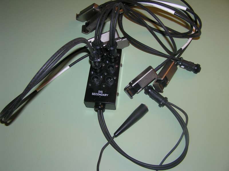
I picked up this set of leads to monitor ignition output on a scope:
.
The idea is that one can display a chain of ignition pulses. Variations in amplitude can help identify misfires etc. Unfortunately, it turns out these are designed to work with a particular specialty scope, don't have BNC connectors, etc. So I'd like to adapt it.
The big black box is nothing more than a j-box. Here's the schematic:
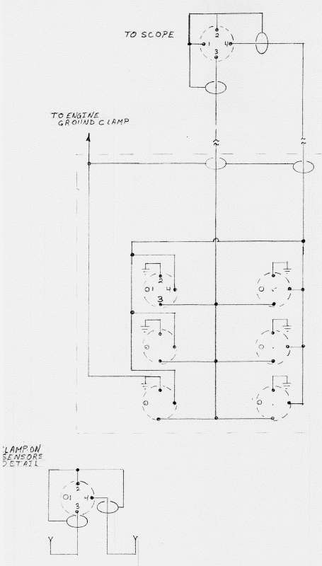
The pickups are nothing more than a piece of copper soldered to the co-ax conductor -- basically, an antenna. Those are ganged together into two outputs. Here's the problems I identified:
There's no way to identify which cylinder is displayed and it requires both channels to display all cylinders. (I want them all on one so the other channel is available to monitor another system at the same time)
Waste spark systems show an inverted waveform on half the cylinders.
If there is a flaw or failure of the ignition wire insulation, the scope inputs will be subjected to tens of KV -- more than most scopes can handle!
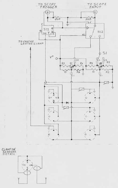
I've been playing around with some ideas, and come up with the following modifications:
However, I don't really know what I'm doing, and would appreciate some help with this -- a better design, or help figuring values for "my" design (cobbled together from some circuit fragments I found on the net.)
Here's what I'm trying to accomplish: First of all, MOVs for the inputs in case of insulation failure.
Second, a diode on one input to separate out a trigger source.
Next, Q2 is a phase splitter with one output 180° from the input. The two outputs feed S1, to correct the waveform for waste spark systems. Q1 is just there to ensure the other bank is processed equally.
IC1 is a toggle flip-flop to divide the trigger pulses by two. This in turn toggles IC2 to alternate banks so the waste spark will be ignored. That is, only pulses from bank 1 will be passed to the output (ignoring waste spark from bank 2) then when the waste trigger occurs it is suppressed and IC2 feeds bank 2 to the output (suppressing waste spark from bank 1).
Well, that's the theory anyway. My projects always work well in theory...
Measured raw voltage, using 10x probes connected to the connector pins, ranged from 15v to 120v peak-to-peak. For powering these mods, I think I'd either like to use a 9v battery or a couple of alligator clips right off the vehicle's battery.
If it's not completely obvious yet, I don't know what I'm doing. HELP!!!
Please. 


