Thanks everyone

I can't see how ST can run the ADC (to get the two cal values) at anything else than Vcc, simply because some packages have no other option. And what Vcc? Why use anything other than 3.3V since almost everybody will be using 3.3V.
But if indeed those two readings were done at some other Vref, the whole sloping line will be shifted, both absolutely up/down and in the slope. So what the hell can I do?
What is the meaning of the CAL value in this?
CAL is the internal reference calibration value read out of system memory (from VREFINT_CAL). What does this mean, if not using internal Vref for anything?
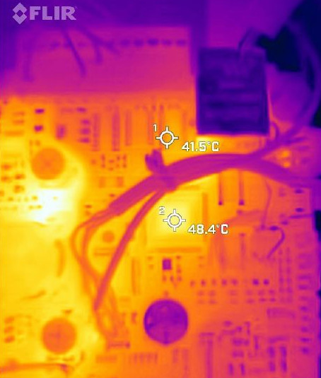
The top of the chip is at +48C. The sensor reading works out at +59C.
I can't easily do a measurement within milliseconds of power application because I would have to set up a UART; no way to do Cube debugs (SWV or anything else, or USB) until a few secs later.
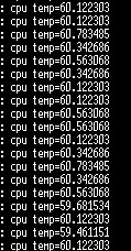
The timing should be OK. I am using the slowest ADC S/H option, 25us, plus a 20us wait after ADC init (when the bit for turning on the sensor is set). I could do filtering (say 100 readings, add-up and /100, for a 10x improvement) but it would slow it down too much for some scenarios. I tried it; noise is down to about 0.3K. Noise is ~1K (200ms intervals):
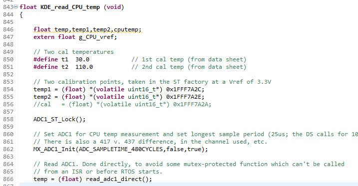
In this code
I get these values
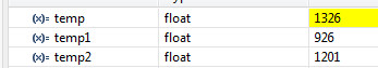
The 1326 would be > 110C but is then scaled by 2.5/3.3 as described above, to yield around +60C.
Yes this chip is fully loaded, with ETH and everything
With ETH off, the temp drops about 2K. but of course the PHY is off-chip.
There is a vast number of people on the web going around in circles on this e.g.
https://electronics.stackexchange.com/questions/324321/reading-internal-temperature-sensor-stm32although there somebody states
Every device has two ADC raw values taken at 30 °C and 110 °C at 3.3 V stored internallywhich confirms what I am thinking.


