I'm slowly losing my mind with the Solartron 7081.
I bought a 'for repair' unit, thinking that the problem wouldn't be significant... I won't bore you with tales of a multimeter which had obviously been dropped at some point in its life. Or the story of inexplicable problems and their solutions. In the end, I managed to get it working again so that I could start testing it.
I checked the 10V range against one of my most stable and quiet references - a Dr. Frank LTZ1000 build. Sadly, what I saw was 4ppm popcorn noise:
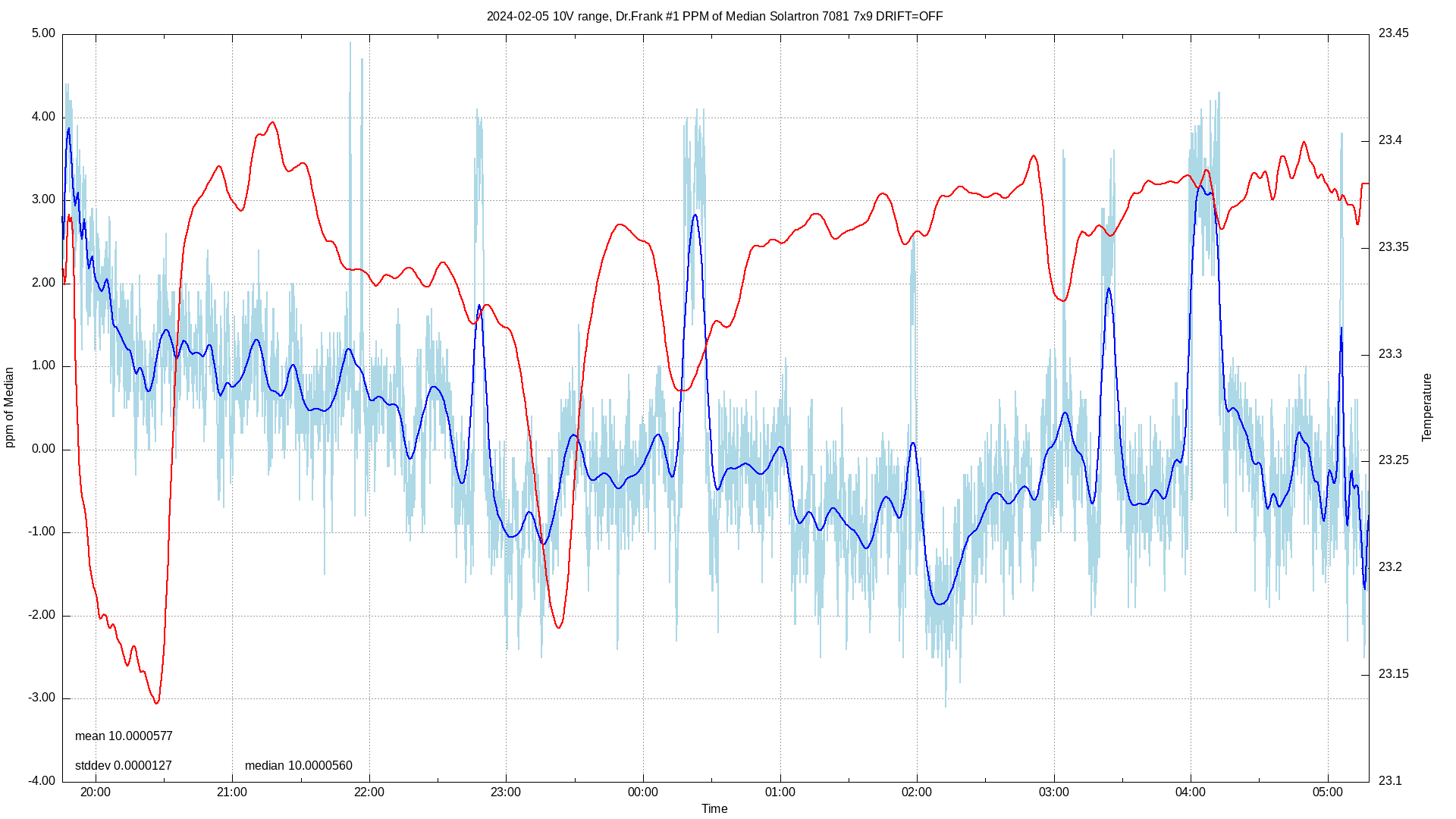
After eliminating every other component in the reference circuitry I was forced to accept that my finely aged and selected by greybeards reference diode had surrendered its ppms and stability.
I know. The answer is "put an LTZ1000 reference in there". That wouldn't be keeping the meter original though, would it? So I found a supplier of new, old stock 1N829 diodes on eBay and threw myself head first into the process of trying to find one golden 1N829 from the six that I'd bought.
I put together my first ever KiCAD project to create a PCB with six 7.5mA current sources, had it made in China, learned about not just double, but triple checking every aspect before committing a design for production, worked around my mistakes and started the selection process.
Two diodes had terrible popcorn noise and were immediately eliminated. The other four had a pair of stars and two which were OK. So I let them age for another 2000 hours... Two of them, according to my Euler Precision LFLNA-80 turned out to have around 0.5µV peak to peak noise.
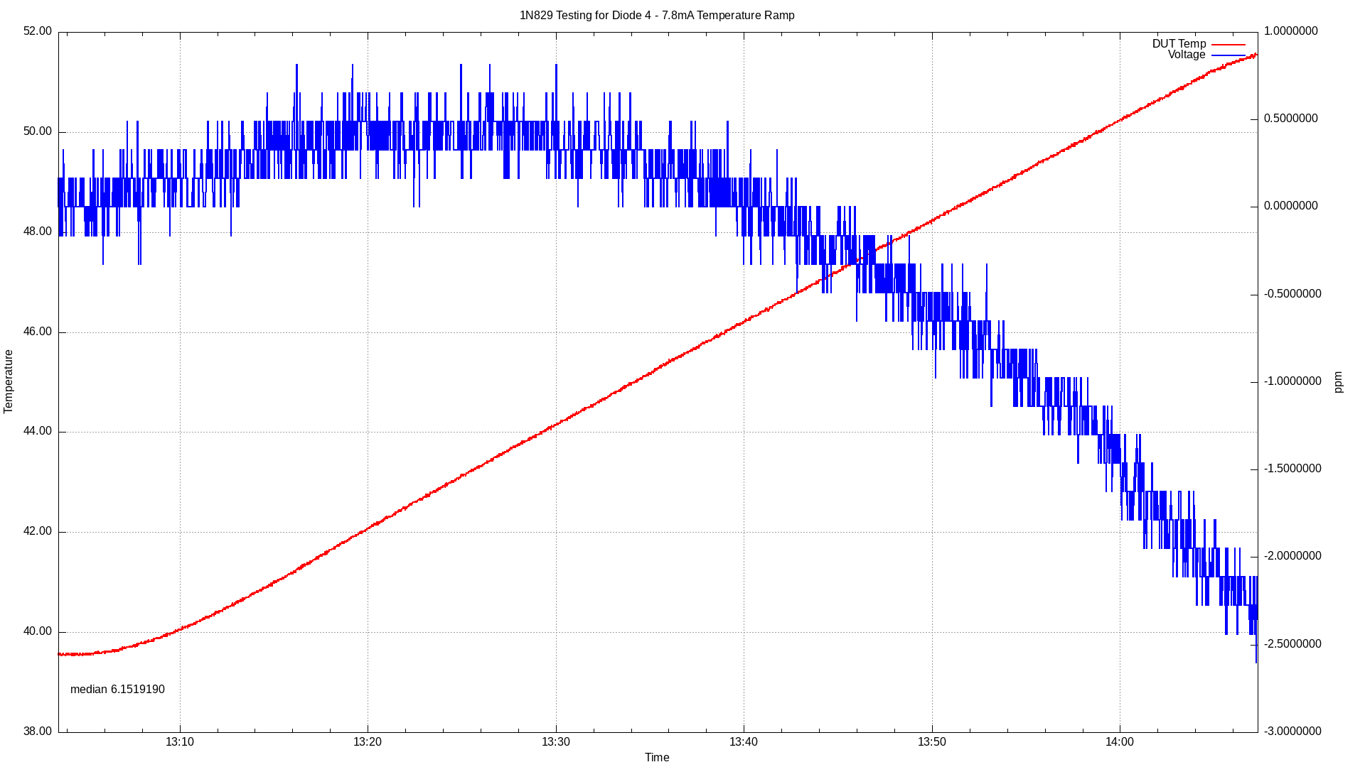
I took the best one and started ramping it from 39ish°C to 51ish°C at increasing current.
I found a magic current for my best diode!
But here's where my problems start.
If I read the Solartron 7081 service manual, in the description of the reference circuit, it talks about the second order tempco correction circuit being centred around the top of the curve being at 27°C. That makes no sense at all. The average internal temperature of my 7081 is between 40 - 45°C depending on the ambient temperature. This meter is a closed case meter with no fans. There is no way that after being powered up for a day that the internal temperature would ever be even close to 27°C!
I looked at the wonderful document that Mickle T had written about his experiments with the 7081. In there, he talks about how the reference circuit works. Following his documentation, I could easily work out how to set the required "Zener Token" value and adjust the resistors involved so that I could set the correct current for my new diode. That turned out to be 7.8mA:
What I can't work out how to do is recalculate the values of resistors R351 and R354. As I now have a current for my diode which places the top of the tempco curve at between 40°C to 45°C - exactly where it needs to be for my meter, I need to know how I can work out what the values of these two resistors should be.
Can anyone help me?


