Author Topic: GPSDO with Rb and XO  (Read 9596 times)

0 Members and 2 Guests are viewing this topic.

Offline ArthurDent

  • Super Contributor
  • ***
  • Posts: 1193
  • Country: us
Re: GPSDO with Rb and XO
« Reply #25 on: December 17, 2019, 11:53:56 pm »
I guess I’m not quite as concerned as some others about relying on the long term measurements I get by using the GPS satellite system. I haven’t had any problems with the level of accuracy I see, at least for quality of the standards I now own. One of the GPSDOs that I mainly rely on is a modified EBSCTM (NTPB15AA) with one of the typical Tbolt displays added and a SMPS built into the unit. Lady Heather treats it pretty much like a Tbolt and uses almost all of the same commands. I’ve had this running for a few years and have a lot of confidence in it. Here is a graph from it that covers almost a day.

I also use a couple of modified Thunderbolt with no internal OCXOs that I use to check the drift and stability of 10Mhz oscillators that I want to test. I can connect both the 10Mhz and the EFC from the Tbolt to the oscillator or to just check drift, only connect the 10Mhz, and let the oscillator free run. Below is a graph of one of my Rb standards I was adjusting using this method. The white trace basically displays the jitter and that trace stays very close to the reference line while the purple PPS trace displays the accumulated drift.  Initially the frequency was low and after about 3 hours I made an adjustment and overcorrected a little and after about another 3 hours I decreased the frequency and my guess was pretty close.

Some of the GPSDOs I own don’t output all the information that the Tbolts do so I can run both the GPSDO under test and the modified Tbolt, feeding the 10Mhz from the GPSDO under test to the modified Tbolt and let the Tbolt graph the output to get almost all of the same information except for the DAC data which in this case would be meaningless. 
 

Offline FriedLogic

  • Regular Contributor
  • *
  • Posts: 115
  • Country: gb
Re: GPSDO with Rb and XO
« Reply #26 on: December 18, 2019, 10:53:14 pm »
I also use a couple of modified Thunderbolt with no internal OCXOs that I use to check the drift and stability of 10Mhz oscillators that I want to test. I can connect both the 10Mhz and the EFC from the Tbolt to the oscillator or to just check drift, only connect the 10Mhz, and let the oscillator free run.

I do sometimes regret not stocking up on a few thunderbolts - they're useful as test gear as well as GPSDOs.

These plots are from a test that I did with a temperature controlled and air pressure compensated Efratom LPRO against a sawtooth corrected M12+T GPS. The diurnal variations on the GPS show up quite well against the LPRO. Red/pink traces are the LPRO frequency.

1000s averages were used for these plots, so the stats plots are a bit different/lower than they would be with the 1s data.

« Last Edit: December 19, 2019, 01:04:15 am by FriedLogic »
 

Offline tkamiyaTopic starter

  • Super Contributor
  • ***
  • Posts: 2178
  • Country: us
Re: GPSDO with Rb and XO
« Reply #27 on: December 19, 2019, 02:54:57 am »
I guess I’m not quite as concerned as some others

Let's NOT get too reasonable here.   :-DD

Happy Holidays!
« Last Edit: December 19, 2019, 02:57:03 am by tkamiya »
 

Offline tkamiyaTopic starter

  • Super Contributor
  • ***
  • Posts: 2178
  • Country: us
Re: GPSDO with Rb and XO
« Reply #28 on: December 19, 2019, 03:00:02 am »
I have a quite a bit of PRS-10 and just recently, bought some T-bolt.  One with older OCXO and 3 with Trimble OCXO.  Looks like surplus is starting to dwindle, so got some for myself.  My main standard is basically the same with Arthur's.  GPSTM.  (Nortel OEM t-bolt)

Regrettably, I made few mistakes along the way.  I was so pleased with GPSTM, I bought 5 more at very very reasonable prices.  Unfortunately, these are made by different OEM.  It has some crazy jitters.  So they are now sitting in storage bin.

I have Cs but I don't have very much trust in it.  It's over 20 year old with an original tube.  It locks but a reliable source told me, 4040A is particularly prone to temperature induced drift. 
« Last Edit: December 19, 2019, 03:04:42 am by tkamiya »
 

Offline testpoint1

  • Frequent Contributor
  • **
  • Posts: 397
  • Country: us
Re: GPSDO with Rb and XO
« Reply #29 on: December 19, 2019, 02:45:08 pm »
I have a quite a bit of PRS-10 and just recently, bought some T-bolt.  One with older OCXO and 3 with Trimble OCXO.  Looks like surplus is starting to dwindle, so got some for myself.  My main standard is basically the same with Arthur's.  GPSTM.  (Nortel OEM t-bolt)

Regrettably, I made few mistakes along the way.  I was so pleased with GPSTM, I bought 5 more at very very reasonable prices.  Unfortunately, these are made by different OEM.  It has some crazy jitters.  So they are now sitting in storage bin.

I have Cs but I don't have very much trust in it.  It's over 20 year old with an original tube.  It locks but a reliable source told me, 4040A is particularly prone to temperature induced drift.

for Cesium, only 5071A
 

Offline tkamiyaTopic starter

  • Super Contributor
  • ***
  • Posts: 2178
  • Country: us
Re: GPSDO with Rb and XO
« Reply #30 on: December 29, 2019, 05:21:40 am »
If I could afford a working 5071A, I'd have one.  All I have is WORKING 4040A and DEAD 5071A.

I have been running a 14 day test of PRS-10 being steered by a GPSDO.  It's only half way through but it is showing some promise.  Sadly though, this won't be definitive as house standard is yet another GPSDO.  Once this is done, I'll do the same test with Cs being the standard. 

I may actually run a 30 day test next time.  I still haven't run into a clear point where Adev starts to go up.
 

Offline edpalmer42

  • Super Contributor
  • ***
  • Posts: 2314
  • Country: ca
Re: GPSDO with Rb and XO
« Reply #31 on: December 29, 2019, 08:35:06 am »
If I could afford a working 5071A, I'd have one.  All I have is WORKING 4040A and DEAD 5071A.

Datum/FTS made drop-in replacements for many of the HP Cs tubes.  I don't know how much interfacing would be required to move the tube from your 4040 to the 5071A or if it's even practical, but it might be worth exploring.

Quote
I have been running a 14 day test of PRS-10 being steered by a GPSDO.  It's only half way through but it is showing some promise.  Sadly though, this won't be definitive as house standard is yet another GPSDO.

What?  A properly working GPSDO is the best standard available to mere mortals.  The USAF continuously monitors the satellites and corrects their frequencies as necessary.  The result is a system that's more stable than Cs.  So, if you have multiple GPSDOs of different types that agree with each other, you can be sure that they are on frequency.

Quote
I still haven't run into a clear point where Adev starts to go up.

Of course not!  A rising Adev suggests aging.  Once you get past the OCXO range and into the GPS range of the graph, you should never see a rising Adev on a GPSDO.  The only thing you'll see is a flat Adev which represents whatever white noise exists in the system.  Typically, this will be in the e-13 range or lower.

You might see things like diurnal effects that look like aging if you don't run the graph long enough.


Offline tkamiyaTopic starter

  • Super Contributor
  • ***
  • Posts: 2178
  • Country: us
Re: GPSDO with Rb and XO
« Reply #32 on: December 29, 2019, 05:41:53 pm »
GPSDO is accurate to only about E-08.  Only when one integrates over long time, it will reach somewhere between E-12 to E-13 depending on the quality of OCXO.  So I have two GPSDO, one house standard and one DUT.  Every second, comparison is made.  That comparison is accurate only to E-08. (instantaneously)  But that's not exactly what I'm doing....  That's just my house standard.

Take a look at this release note:  https://www.thinksrs.com/downloads/pdfs/catalog/PRS10c.pdf

Page 2, top left.  That's what I'm doing.  PRS10 is supposed to drift/age minutely and adev will head up.  It is supposed to, then, get hammered down by GPSDO.  I haven't seen that point, yet.  I am seeing gradual up trend but confidence range is too large to interpret it.  It looks like settling down to 4xE-12.

Please note, SRS's note is Allan VARIANCE and the tool I'm using shows Allen Deviation.  I know the difference is square root.  I'm trying to wrap head around this now.  But overall, I'm very pleased. 

Yes, I looked at that replacement tube.....  Symmetricom makes them now.  I saw somewhere, the price is about USD40K for standard tube.  I don't know about transplanting.  I'd rather leave that tube as-is, where is.
 

Offline Leo Bodnar

  • Frequent Contributor
  • **
  • Posts: 810
  • Country: gb
Re: GPSDO with Rb and XO
« Reply #33 on: December 29, 2019, 05:57:33 pm »
"Root Allan Variance" is the same as Allan deviation, it just sounds a bit more posh.
Leo

Please note, SRS's note is Allan VARIANCE and the tool I'm using shows Allen Deviation.  I know the difference is square root.  I'm trying to wrap head around this now.  But overall, I'm very pleased. 
« Last Edit: December 30, 2019, 08:45:32 am by Leo Bodnar »
 

Offline tkamiyaTopic starter

  • Super Contributor
  • ***
  • Posts: 2178
  • Country: us
Re: GPSDO with Rb and XO
« Reply #34 on: December 29, 2019, 06:06:23 pm »
Woooo....  That sounds NICE!

So that IS the same thing then. 
« Last Edit: December 29, 2019, 06:09:22 pm by tkamiya »
 

Offline kutte

  • Contributor
  • Posts: 35
  • Country: de
Re: GPSDO with Rb and XO
« Reply #35 on: December 29, 2019, 06:36:51 pm »
hi Tkamiya, this article of Ulrich Bangert
http://www.ulrich-bangert.de/AMSAT-Journal.pdf
provides an excellent introduction to the stability of oscillators and frequency standards.
But sorry it is available only in German but very welll worth any efforts to try a translation.
Dual mixer method for measuring stability is explained as well as understanding Allan deviation and the usefulness
of coupling OCXOs and GPS.
have fun Kutte
« Last Edit: December 29, 2019, 06:39:26 pm by kutte »
 

Offline edpalmer42

  • Super Contributor
  • ***
  • Posts: 2314
  • Country: ca
Re: GPSDO with Rb and XO
« Reply #36 on: December 29, 2019, 07:17:59 pm »
In a quick unscientific test, I measured the frequency of my Tbolt.  The connection was:  Tbolt -> 10 MHz low pass filter -> Fluke PM6681 counter.  1 sec. gate time, referenced to HP 5065A.  Variations in frequency were around +- 1 millihertz, i.e. 1e-10.  Changing the gate time to 5 sec.  reduced the variations to around 0.2 millihertz or 2e-11.

As you stated, integrating the GPSDO signal over long periods improves the results.  That's exactly what an Allan Deviation graph is showing.  The only way you will see a rising graph is if the long-term average frequency is changing.  That won't happen with GPS.  So since your reference is also a GPSDO, the only thing left that could be changing is your measurement system.

The PRS10 document wanders back and forth between Variance and Deviation.  Very confusing.  There's no date on it.  I wonder if it dates back to before Selective Availability was disabled?  The price it quotes is the same as the price in June 2000.  The same graph was also used at that time.  Selective Availability was disabled in May 2000.  Selective Availability would significantly increase the noise on of any GPS-derived measurement.  Long duration measurements wouldn't be affected, but short-term measurements would suffer.


Offline Leo Bodnar

  • Frequent Contributor
  • **
  • Posts: 810
  • Country: gb
Re: GPSDO with Rb and XO
« Reply #37 on: December 29, 2019, 07:21:09 pm »
If you are diving much below 10-13, remember, that GPS time is steered towards UTC (modulo 1s) but can be as far away as 10ns at times.  I don't have a clear idea of what ADEV plot of UTC-GPS looks like, only have standard deviation figures from https://www.gps.gov/governance/advisory/meetings/2017-11/powers.pdf
This might be only of academic importance but interesting anyhow.
Notice, that both GPS time and UTC derived from GPS transmission are 1ns RMS away from UTC(USNO.)
Leo

Offline thinkfat

  • Supporter
  • ****
  • Posts: 2154
  • Country: de
  • This is just a hobby I spend too much time on.
    • Matthias' Hackerstübchen
Re: GPSDO with Rb and XO
« Reply #38 on: December 29, 2019, 09:49:12 pm »
Hm. If you get 1e-8 only with a GPSDO, for small tau (< TC), that would hint that the oscillator of the GPSDO is rubbish. With a good OCXO you should get into the 1e-11 range.
Everybody likes gadgets. Until they try to make them.
 

Offline tkamiyaTopic starter

  • Super Contributor
  • ***
  • Posts: 2178
  • Country: us
Re: GPSDO with Rb and XO
« Reply #39 on: December 29, 2019, 10:55:33 pm »
I misspoke.  1 pps out of GPS is 10^-8 range at low tau.  You are absolutely correct that good OCXO should give ^-11 ish.
« Last Edit: December 29, 2019, 10:58:16 pm by tkamiya »
 

Offline tkamiyaTopic starter

  • Super Contributor
  • ***
  • Posts: 2178
  • Country: us
Re: GPSDO with Rb and XO
« Reply #40 on: December 29, 2019, 11:02:02 pm »
There is something quite addictive about these stuff....  oh oh....  am I becoming a time-nuts?
 

Offline tkamiyaTopic starter

  • Super Contributor
  • ***
  • Posts: 2178
  • Country: us
Re: GPSDO with Rb and XO
« Reply #41 on: December 29, 2019, 11:11:12 pm »
Edpalmer42,

Actually, I'm measuring an Adev of PRS10 output steered by GPSTM (Nortel version of T-bolt) using a reference of another GPSTM.  What I can summarize from that confusing SRS release note is that once aging takes over and the graph starts to head UP, GPS should bring it down.  So aging will be non-issue.  So, this is NOT quite GPS vs GPS. 

I found something interesting.  My graph indeed turns UP at one point but I noticed it NEVER touches 1E-11.  Then I turned on the error bar.  Aha!  Margin of error (not enough samples) is affecting the graph.  I have this running for 14 days and this is the 8th day.  It has been like this for 3 days or so.  (almost touches 1E-11)  So if I were to run this forever, I expect it will settle somewhere around 4E-12.

Sorry about bad quality photographs.  The measurement machine is in different subnet. 
 

Offline edpalmer42

  • Super Contributor
  • ***
  • Posts: 2314
  • Country: ca
Re: GPSDO with Rb and XO
« Reply #42 on: December 29, 2019, 11:43:08 pm »
I misspoke.  1 pps out of GPS is 10^-8 range at low tau.  You are absolutely correct that good OCXO should give ^-11 ish.

Okay, now I see what you're saying.  Yes, if you measure the Allan Deviation of a raw GPS receiver, rather than a GPSDO, you can expect an ADEV value of around 1e-8 @ Tau = 1sec.  Newer designs do somewhat better.  From there, it improves at a slope of -1, i.e. one decade improvement of ADEV for every decade of time until it reaches the white noise limit.  Beyond that, the value is a constant.

But remember that your reference GPSDO has already integrated all that out.  It has climbed down the ADEV curve and is giving you an OCXO-smoothed signal that is on frequency.  The short-term noise is due to whatever oscillator is in the GPSDO.  In my case, the 1e-10 value is the noise of the OCXO in the Tbolt.  So, if your primary concern is frequency, you're there.  You have to set the gate time to average out the short-term noise to a level that's appropriate for your needs.

Since you're using a GPSTM to feed your PRS10, you're using the PRS10 as a clean-up oscillator to try to improve the output of the GPSTM and keep the PRS10 on frequency.  I don't know if there's enough info in the PRS10 manual to determine if this will give you a cleaner signal, but it should keep it on frequency.  The shape of the ADEV curve will depend on the PRS10's internal disciplining algorithm.

By the way, you're not 'becoming' a time-nut.  You passed that threshold a long time ago!  ;)


The following users thanked this post: FransW

Offline tkamiyaTopic starter

  • Super Contributor
  • ***
  • Posts: 2178
  • Country: us
Re: GPSDO with Rb and XO
« Reply #43 on: January 14, 2020, 12:35:15 am »
My experiment has nothing to do with Planck Time, or anything of (such a tiny) magnitude.  According to SRS PRS10 manual, PRS10 has an AllenDev that bottoms then goes up due to drift.  The same manual says adding PPS from GPS steers Rb and eliminate the drift part of Adev.

I'm trying to do just that.

I did have a go at it, and results are rather disappointing.  With PPS, the Allen dev of PRS-10 is 10 times worse at all interval!  Oddly enough, partial graph collates fairly well.  I did not tune anything and left everything as default.  This is the first try.  By default, PRS-10 comes standard with loop gain and loop constant suitable for GPS, so I went with it.

Now that I have this result, I am at a phase to think through what might have gone wrong.  Ground loop and noise on PPS line comes first to my mind.  I was rather sloppy in this area.  I made the voltage where it's needed willy-nilly.  I should be more careful.  I didn't appreciate the level of scale I was dealing with.  Also, GPS I used was of unknown nature.  I now have few T-bolt, so I'll use that next.

I am not going to upload the graph....  It's so SO disappointing....... :palm:
 

Offline thinkfat

  • Supporter
  • ****
  • Posts: 2154
  • Country: de
  • This is just a hobby I spend too much time on.
    • Matthias' Hackerstübchen
Re: GPSDO with Rb and XO
« Reply #44 on: January 14, 2020, 08:48:50 am »
My experiment has nothing to do with Planck Time, or anything of (such a tiny) magnitude.  According to SRS PRS10 manual, PRS10 has an AllenDev that bottoms then goes up due to drift.  The same manual says adding PPS from GPS steers Rb and eliminate the drift part of Adev.

I'm trying to do just that.

I did have a go at it, and results are rather disappointing.  With PPS, the Allen dev of PRS-10 is 10 times worse at all interval!  Oddly enough, partial graph collates fairly well.  I did not tune anything and left everything as default.  This is the first try.  By default, PRS-10 comes standard with loop gain and loop constant suitable for GPS, so I went with it.

Now that I have this result, I am at a phase to think through what might have gone wrong.  Ground loop and noise on PPS line comes first to my mind.  I was rather sloppy in this area.  I made the voltage where it's needed willy-nilly.  I should be more careful.  I didn't appreciate the level of scale I was dealing with.  Also, GPS I used was of unknown nature.  I now have few T-bolt, so I'll use that next.

I am not going to upload the graph....  It's so SO disappointing....... :palm:

Hm. It's difficult to imagine noise on the 1PPS signal being a factor. You'd need quite a lot of energy to disturb it.

A standard navigation type GPS would have quite a lot of jitter on the 1PPS and since the PRS-10 is not communicating with it, it can not apply quantization correction (sawtooth correction). That will require a lot of averaging to compensate for. I can imagine the loop constant on the PRS-10 will need tweaking.
Everybody likes gadgets. Until they try to make them.
 

Offline Leo Bodnar

  • Frequent Contributor
  • **
  • Posts: 810
  • Country: gb
Re: GPSDO with Rb and XO
« Reply #45 on: January 14, 2020, 09:41:02 am »
Firstly, any result is a good result - post the graphs please.

Secondly, please explain in details what are you using as a DUT, reference source and measurement setup?

If you were to use the same source to produce 1PPS and to measure ADEV/MDEV against you can probably get better insight into short/mid term behaviour of the control loops.

Leo
 
The following users thanked this post: Theboel

Offline FransW

  • Frequent Contributor
  • **
  • Posts: 270
  • Country: nl
Re: GPSDO with Rb and XO
« Reply #46 on: January 14, 2020, 04:27:43 pm »
Interesting articles:
NIST: https://www.nist.gov/pml/time-and-frequency-division/primary-standard-nist-f1
with picture below
Getting Better All the Time: JILA Strontium Atomic Clock Sets New Records
https://www.nist.gov/news-events/news/2015/04/getting-better-all-time-jila-strontium-atomic-clock-sets-new-records
and: Released February 4, 2010, Updated March 21, 2018
https://www.nist.gov/news-events/news/2010/02/nists-second-quantum-logic-clock-based-aluminum-ion-now-worlds-most-precise

Hackaday: CONFESSIONS OF A REFORMED FREQUENCY STANDARD NUT >>
https://hackaday.com/2018/01/17/confessions-of-a-reformed-frequency-standard-nut/

Mark the progress in the last 50 years.

Quote: There is a seduction to measurement, something that draws you in until it becomes an obsession.
« Last Edit: January 14, 2020, 04:35:13 pm by FransW »
PE1CCN, Systems Engineering, HP, Philips, TEK, BRYMAN, Fluke, Keithley
 

Offline tkamiyaTopic starter

  • Super Contributor
  • ***
  • Posts: 2178
  • Country: us
Re: GPSDO with Rb and XO
« Reply #47 on: January 14, 2020, 11:11:15 pm »
By popular demand, here's the graph and the details.

The graph was made by measuring each DUT, one at a time, by HP53132A counter.  Gate time was set to 1s so that I will get 12 digit resolution.  HP53132A had GPSTM by Nortel (basically a T-bolt inside) as sync source.  Between the counter and the GPSDO are two distribution amp and RG58.  Antenna is 28dbi gain type and goes through a series of distribution amps, 58536A.  It feeds both the timing source and the below GPS.

HP53122A was connected to TimeLab (latest edition) via RS232C and recorded as "Talk only" device. 

DUT #1 is a PRS-10 at default setting connected to 1 pps by GPS.  GPS is this one:
https://www.tindie.com/products/nsayer/gps-clock/  Version 3, I believe.  It uses a Skytraq Venus838LPx-T chip, which is a timing grade chip.  I confirmed PPS is valid and PRS10 recognizes it.

DUT #2 is just a PRS-10 (same one).

Common to both is an internal distribution module for PPS _OUTPUT_ which consists of 74AC07 and 10MHz output distribution amp, which is an unmodified video distribution unit. 

Power supply situation is a mess.
24V comes from linear regulator and feeds PRS10
That 24V goes through 7505 3 terminal regulator, becomes 5V and feeds 74AC07
There is a separate 12V switching supply that feeds the video amp.  At the same time, it goes through a buck converter and feeds the GPS module (the one that feeds PRS10).

Now the graph....
Blue line is DUT #1  (14 days)
Magenta line is DUT #2 (3 days)

Please note, there is a waviness around 10s.  If I do modified Allen, these are obvious impact from mains.  It kind of averaged out now but it was obvious (In modified Allen) in first few days.

What I am realizing now is that I didn't pay any attention to ground loops and ground points.  There is a path for power which has multiple (duplicate) connections to the cabinet, and there is a signal ground which is connected willy-nilly.  I definitely revisit this.

Also, from datasheet and schematic, I can see this is a timing grade implementation but I have no other data.  I used this because I wanted a time display.  It may be worthwhile to substitute a known unit, such as T-bolt, for if nothing else, verification.  (or as suggested, use the same timing source as the counter)

Another thing is phase shifting through dist amps and coax.  I could use a dedicated setup just for this, which will eliminate the possibility.  Also, I need to eliminate dist amps for outputs for purpose of measurement as these are unknown entity.
 

Offline tkamiyaTopic starter

  • Super Contributor
  • ***
  • Posts: 2178
  • Country: us
Re: GPSDO with Rb and XO
« Reply #48 on: January 14, 2020, 11:20:50 pm »
By the way....

I am aware of issues using GPSDO to measure something supposedly better than GPSDO alone.  But this is the best I can do.  I do have an older Cesium but its stability and accuracy is very much in doubt.  In fact, I have no way to measure that conclusively, either. 

I was expecting something similar to what is described in PRS10 literature.  It came out nowhere close.
(please see a graph on page 3)
 

Offline edpalmer42

  • Super Contributor
  • ***
  • Posts: 2314
  • Country: ca
Re: GPSDO with Rb and XO
« Reply #49 on: January 15, 2020, 05:10:33 am »
There's more that's right with your graphs than you might think.

Remember that at any value of Tau, an Allan Deviation graph shows you an RMS combination of the performance of your measurement system, your reference, and your DUT (Device Under Test).  In this case, you could say we have two DUTs, but that's okay.  For us hobbyists, our measurement system is typically the worst part of the system so it shows up first.  If GPS is involved, you can usually pick out its contributions.

Let's start at Tau = 1 sec.  The red graph shows ~ 3e-11.  The 53132A is spec'ed as having a 150 ps resolution.  Your measurement of 30 ps means that the counter is doing averaging.  That may be okay.  I never use frequency for measurements like this because I'm always suspicious of things like that.  They tend to make things look better than they really are.  I prefer a nice, clean, simple time interval.  But, even so, it's the worst performer so from Tau = 1 sec. up to Tau = 10 sec. the 53132A is all you're seeing because if you measure its noise floor, that's what you will see.  [1]  So we know that the PRS10 must have a lower (better) ADEV.  But why is the blue graph 10 times worse?  We know it's not the counter or the PRS10, so it has to be the GPS or perhaps your test setup.  Check the settings on the counter.  If you're triggering on a sine wave, you probably want AC coupled triggering at, or maybe slightly offset from, zero volts.  If you're triggering on a 1 PPS signal, you want DC triggering at about 1/2 of the pulse's amplitude.  Adjust these as necessary for your exact situation.  Inspecting the signals with a 'scope may be beneficial.

Now let's move to Tau = 10 sec.  through to 1000 sec.  First, regarding the wiggles - they're trivial.   If you can get rid of them by grooming your test setup, great!  If not, don't worry about it.  Even though the blue graph is high, it's starting to show GPSDO behaviour.  It first tries to level out.  This shows the performance of the internal oscillator.  It then starts to  curve down exactly as it should.  As it cruises through 1000 sec.  it's right on target.  The red graph also looks good.  Since the graph is basically straight from 1 sec. you know that's the 53132A you're seeing.  So the PRS10 must be better than that.  Then, at 100 sec. it switches and starts rising.  That's the PRS10 rising past the counter and becoming visible.  A rising curve like that suggests aging.  Was the PRS10 - or some other part of the system - still warming up?  Even a locked Rb needs time to settle down.  Also, look at the value.  We're down in the e-13 range!!!

Now let's look around 3000 - 4000 sec.  Here the blue graph goes off the rails.  It looks like it's NOT being disciplined anymore.  I don't know what to make of that.  More investigation would be required.  But the red graph looks good.  Despite the apparent aging of the PRS10, the graph turns and follows GPS.  Why?  Because you used the GPSTM as the reference for your 53132A so you have to expect the GPS 'signature' to appear in your data!  That's why I NEVER use a GPSDO as my reference.  A GPSDO is a perfect frequency reference, but it can color your data as we're seeing here.  My old reference was an Efratom FRK Rubidium.  My current one is an HP 5065A Rubidium.  Here's my favorite picture that shows the GPS signature.  Look at the graphs with the bold colors and dots.  Four different types of GPSDO and they all end up running down, to the right, in parallel.
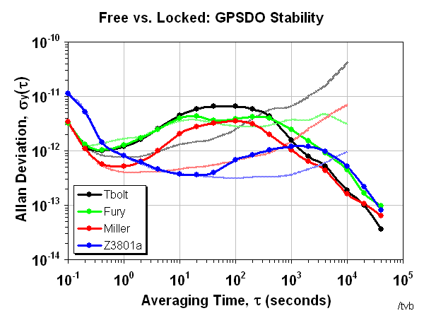


Bottom line here is that your measurements are pretty much what's expected.  The only outlier is the high-Tau performance of your 1 PPS source as shown in the blue graph.

FYI, I've attached a recent data run I did where I compared my FTS 4065A to my HP 5065A.  I included the specified limits for the 4065A.  First you see my measurement system.  Then you see the 4065A.  It's only when you get past 10K seconds that the 5065A starts to appear.

By the way, you don't have to run Timelab in "Talk only" mode.  It natively supports the 53132A.  I don't know if that gives you any additional capabilities or not.

Ed

[1]  I'm really not sure how to measure the frequency noise floor.  Extend the gate time?

You can measure the time interval noise floor by starting with a good quality signal.  If your PRS10 is configured for 1 PPS out, use that, otherwise use the 10 MHz output.  Split the signal in two, preferably with a good 50 ohm splitter, but a BNC T-connector will do.  Feed the two signals through different length coax cables to the Ch 1 and Ch2 inputs of the 53132A.  Measure Time Interval from 1 to 2.  Don't let the cables move or vibrate or change temperature.  Let Timelab collect the data for a few hours.  Your ADEV should show a straight line dropping down with a slope of -1.  This will be a factor in every measurement you take with that counter.

Edit:  I mixed up Time Interval & Frequency measurements/limits.  Hopefully, this straightens things out.   :palm:
« Last Edit: January 15, 2020, 05:59:00 am by edpalmer42 »
 
The following users thanked this post: FransW


Share me

Digg  Facebook  SlashDot  Delicious  Technorati  Twitter  Google  Yahoo
Smf