I resisted posting this since I didn't want to give wrong ideas to the 'original thinkers' in these threads, but since there already is some sort of discussion on how to mimic the behavior of the circuit with a mechanical model and the apparent necessity for an ether (in the mechanical representation) has already been thrown around, I figured... what the heck.
What follows in
NOT a model, and is
NOT an analogy for the circuit. It is
JUST a pictorial way to illustrate the propagation of two different (albeit related) perturbations in the space occupied by the circuit. I call this a magi-mechanical model in that it employs MAGIC to perform its function. (It could probably be constructed by using some sort of active system or some clever use of preloaded springs or whoknowswhat, but... magic is a lot easier.)
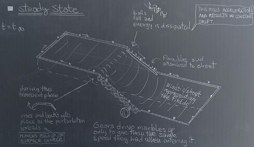
Steady-state and the magi-mechanical modelLet's start with the steady state configuration: we have frictionless rail along which balls can move, a generator that raises these weights from a low level to a higher level, and a resistor that lowers them, converting the potential energy into heat. Heat extracts energy from the system. The whole circuit is attached to an elastic sheet in a manner that I will explain later.
steady state magi-mechanical circuit -
https://i.postimg.cc/qR8D5JcY/screenshot.pngThere are a few considerations to make
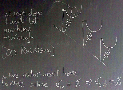
The generatorthe generator can raise weight from the lower end to the higher end, but it only works if there is a ball in the lower end slot. With no ball there, it won't raise s*it.
Moreover, it has a rigid structure and when we 'flip the switch' it will rotate about a pivot point raising the elastic sheet in the process. The balls enter the generator with speed v0 and exit the generator with speed v0.
The rails or conduitsThe rails, or conduits are like a chain, that can be raised or lowered by the nearby generator, but also by the membrane. They are kind of floppy and initially they can only be raised by the generator or the deformation in the elastic sheet, but once a ball gets on the chain link, it will make it snap into a horizontal position, carrying the sheet with them. How? By using magic.
(This is to mimic the propagation of surface charge that is associated with a current inside the wires)
The resistorThe resistor is another floppy (i.e. passive) element that can be raised by the sheet. It features a dissipation mechanism that takes the ball at its upper end and carries it down in a series of cups and dampers that turn the energy into heat.
The ball enters the resistor with speed v0 and also exit the resistor with speed v0.
dissipative mechanism -
https://i.postimg.cc/K8Rqyrrt/screenshot-6.pngThe resistor chain mechanism is weightless and kind of magically glued to the elastic sheet and therefore can be raised by the membrane (whose deformation does not have to take into account the weight of the resistor or the balls inside it).
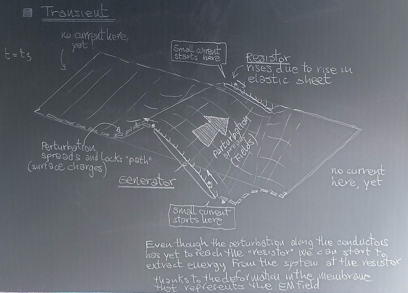
Transient and perturbations in spaceWhat happens during the initial transient? Well, the throwing of the switch is here represented by the tilting of the generator structure. The rigid structure bring the elastic sheet with it and the conduits immediately adjacent will raise locking into horizontal position - the other end will sink down bringing the rail/conduit down with it. A ball will flow into the lower slot of the generator and the motor will start raising the ball in the lower nearby horizontal rail slot. For every ball taken away from the lower side, a ball is put into the higher side of the generator.
As the balls move along the forming 'raised-lowered' rails, new parts of the conduits lock into horizontal place and the deformation of the sheet proceeds (at high but finite speed) ALONG the longitudinal structure of the circuit.
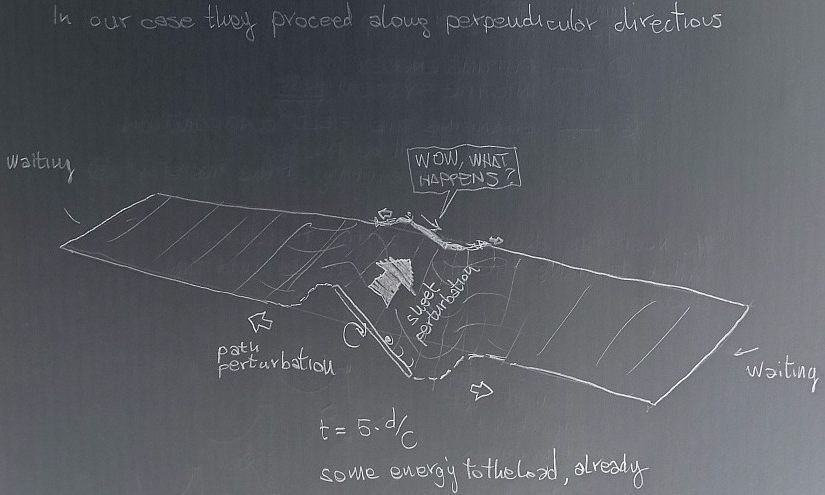
At the same time, though, the elastic sheet raised at the generator side changes the configuration of the sheet in all space around it, including in the transverse direction ACROSS the circuit. This perturbation of the sheet proceeds at a high but finite speed and when it reaches the resistor (much much earlier than the perturbation of the rails started by the generator arrives there) it will raise and lower its floppy body.
This deformation of the resistor (after a time d/c) will make the balls there fall into the dissipative mechanism, and a current will flow into the resistor well before the rail deformation has gone along the full path of the circuit. It will be a much lower current than that attainable at steady state, but a current nonetheless is flowing.
transient with two perturbations -
https://i.postimg.cc/HsPz38Dn/screenshot-3.pngAlso, the equivalent of KCL is dead here. We can have a current in the lower leg and a different current in the upper leg with no current at all in the rest of the circuit. And no, the balls are not one attached to one other, there is space for local accumulation and rarefaction. Only at steady state we can get a uniform distribution along the circuit and the analogous of KCL obeyed.
Not a friggin' transmission lineWhat is the purpose (in my deranged mind) for this magi-mechanical model? Illustrate the fact that we have two perturbations that proceed along different directions and that the transmission line model does not consider that 'complication'.
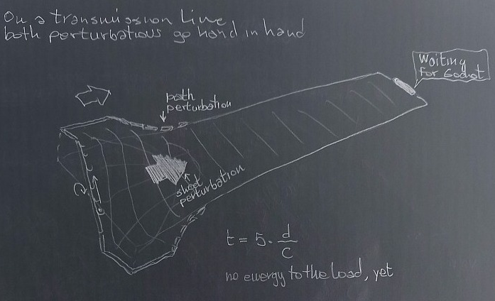
As a matter of fact a transmission line can be 'magi-modeled' by placing the generator on the short leg, and the resistor far away on the opposing short leg.
magi-mechanical model of a transmission line -
https://i.postimg.cc/jjYzkz8x/screenshot-4.pngIn this case both perturbations proceed hand in hand (this is to mimic the use of lumped component for the transverse phenomena) and a transmission line can model the long circuit.
But the magi-mechanical model for the wide circuit shows that in this case one kind of perturbation reaches the load well before the other. The alteration in the fied (here represented by the magical elastic sheet) is accompanied by a local spreading of the second type of perturbation near the resistor, but this is at a level that is well below that attainable at steady state.
magi-mechanical model of NOT a standard transmission line -
https://i.postimg.cc/v8CLVFWx/screenshot-5.pngIs energy actually traveling?A further consideration can be made about the transport of energy. Is energy traveling at all? In my eyes the energy put into the generator is used to change and keep a configuration of the elastic sheet (and borderline conduits) that makes it possible to extract energy in situ at the resistor.
What propagates for sure is the change in the field in all space around the generator. Then we can extract it wherever the new configuration of field allows us to.
(Now, the process of extracting energy can on its own alter the field, and this perturbation will propagate to the generator that might have to put more energy in in order to maintain the status quo).


