IntroDisclaimer: I’m very new to electronics and have only had a scope for a few days, please bear with me

In order to learn more about electronics, I’ve ordered a lot of ICs from AliExpress and I’m just playing around with them. This question is about some weird behavior I’ve seen when playing with the
SN74HC14 Hex Schmitt-Trigger Inverter(Link is to the datasheet).
The goal of the exercise was simply to get the IC working and observe it with my scope.
I’m doing these experiments on a breadboard and powering the circuit with a
HiLetgo Breadboard power supply module set to 5v.
Problem 1: Oscillating inputThe first problem I observed was that the input and output would oscillate when the Schmitt-Trigger changed levels.
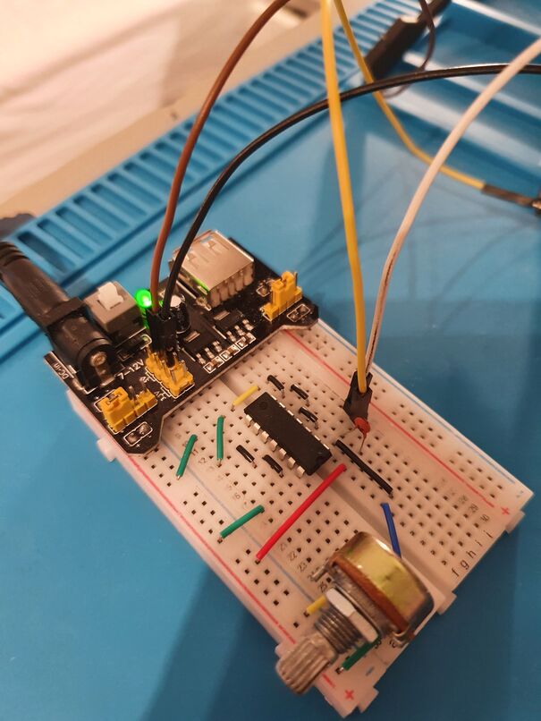
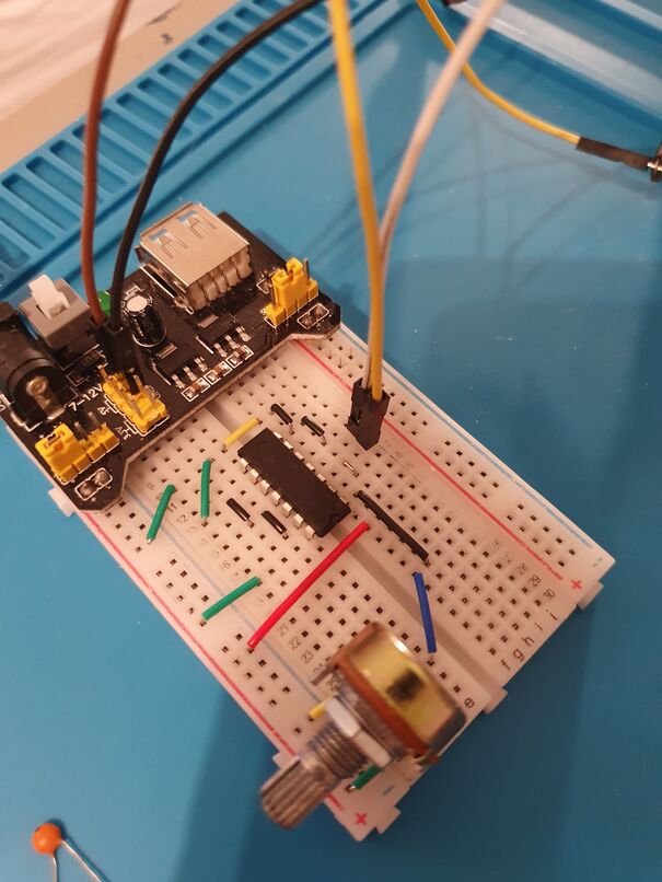
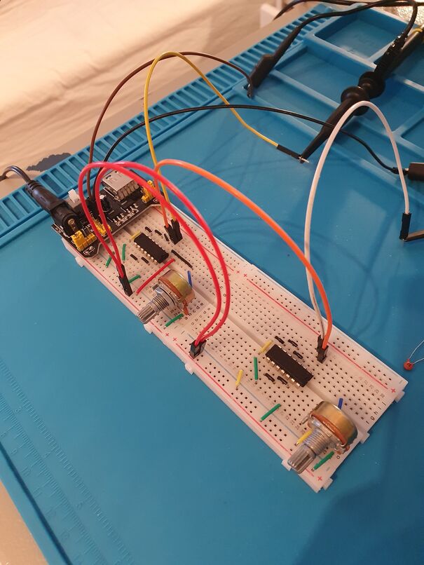
The setup used looks like this:
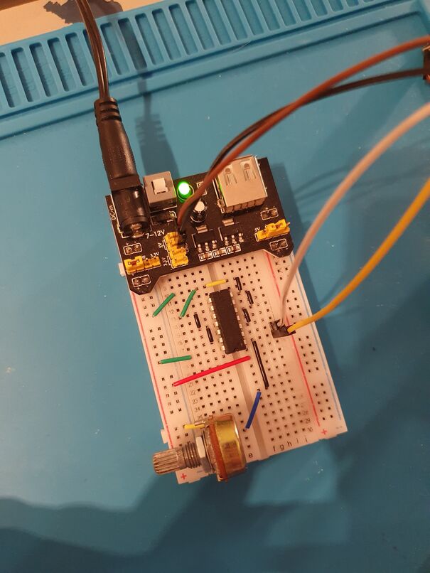
I’ve connected all unused inputs to ground, like the datasheet recommends. I’m using a potentiometer to control the voltage going into the 1A pin. The yellow jumper cable goes to the yellow channel probe on my scope and the white goes to the purple channel. The black and brown channel goes to ground connections on the probes. (The red connector on the middle of the breadboard is not doing anything in this picture, it will come into play later)
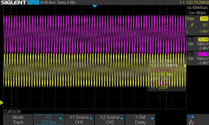
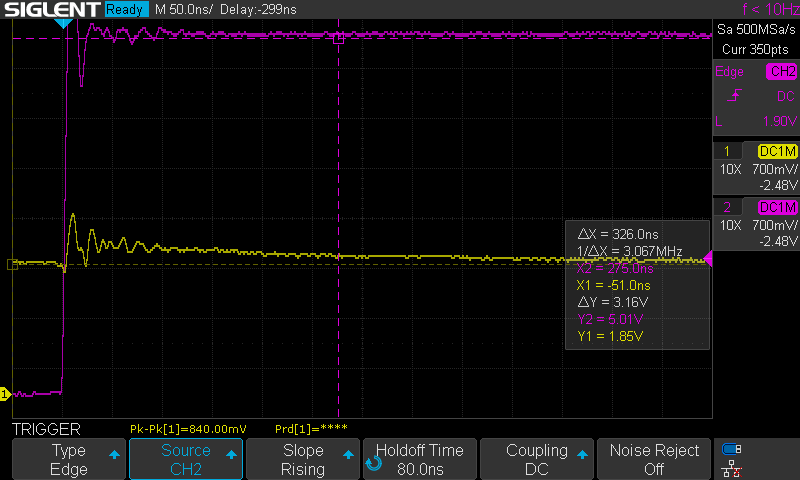
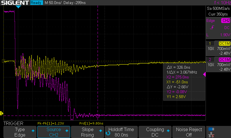
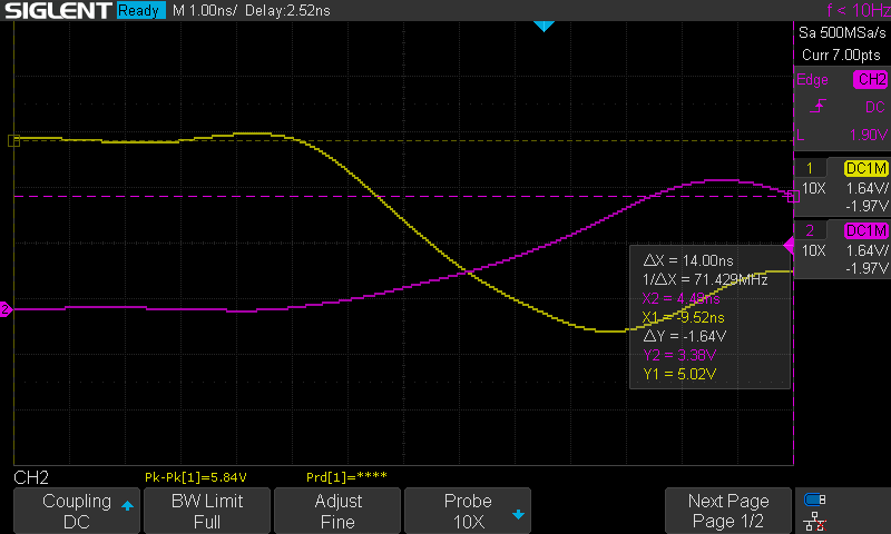
With this setup, I start up my oscilloscope(SDS1104X-E) and I see this, which is expected:

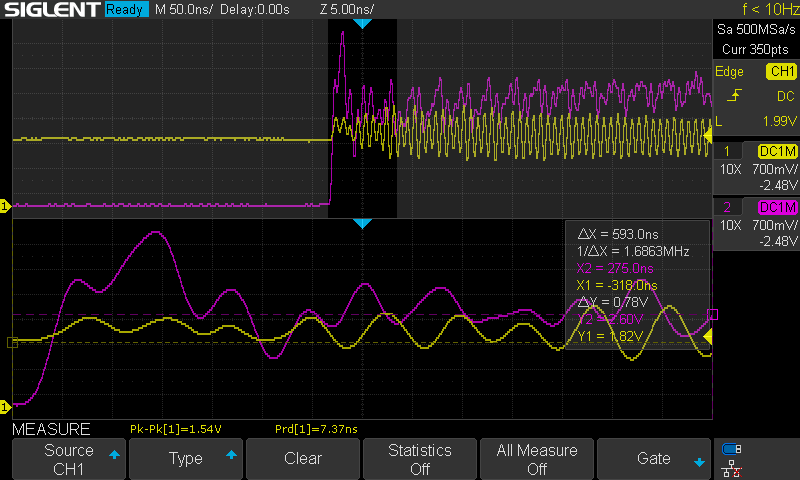
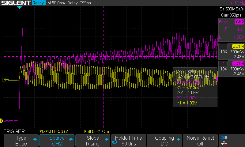
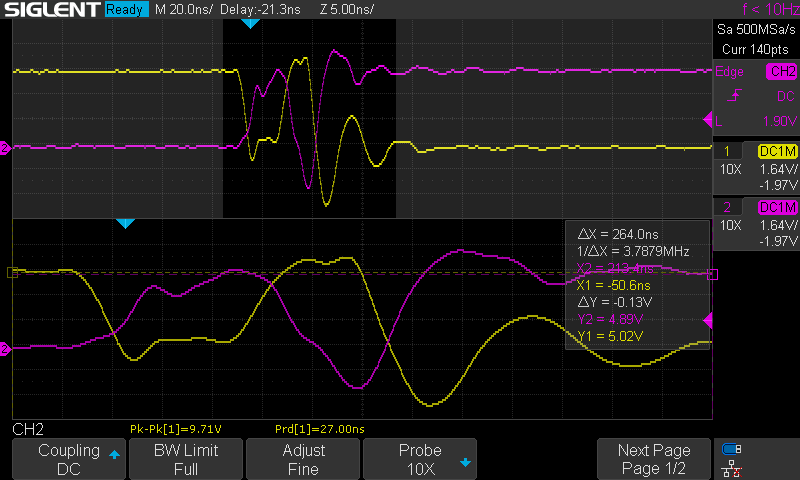
The problem comes when I start adjusting the potentiometer, and the Schmitt-Trigger changes levels:
and
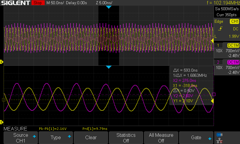
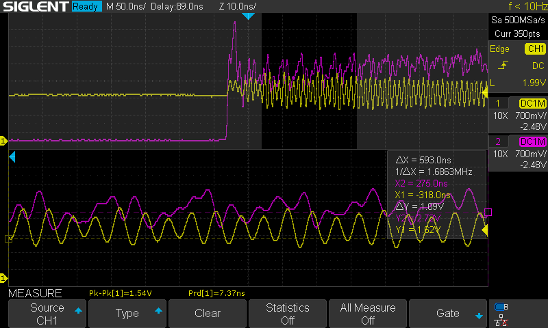
and
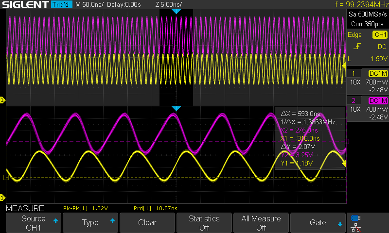
It doesn’t happen all the time, but when it happens, it will get stuck in it. I can then move the input up and down within a range and it will stay oscillation. If I move it too much either way the oscillation will break and the output goes either low or high.
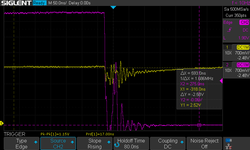
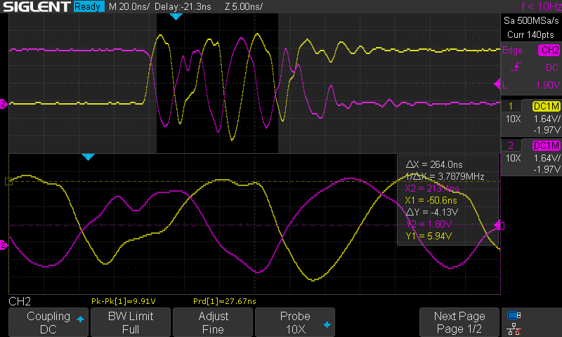
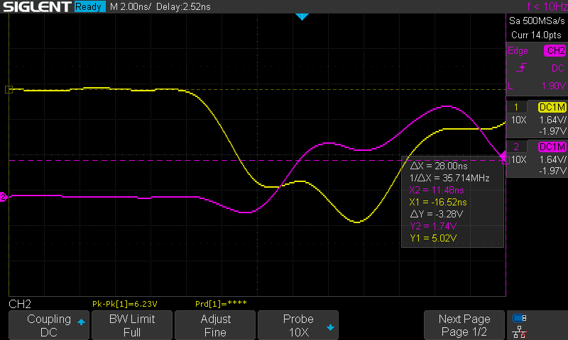
Going from high to low on input and getting oscillation:
and
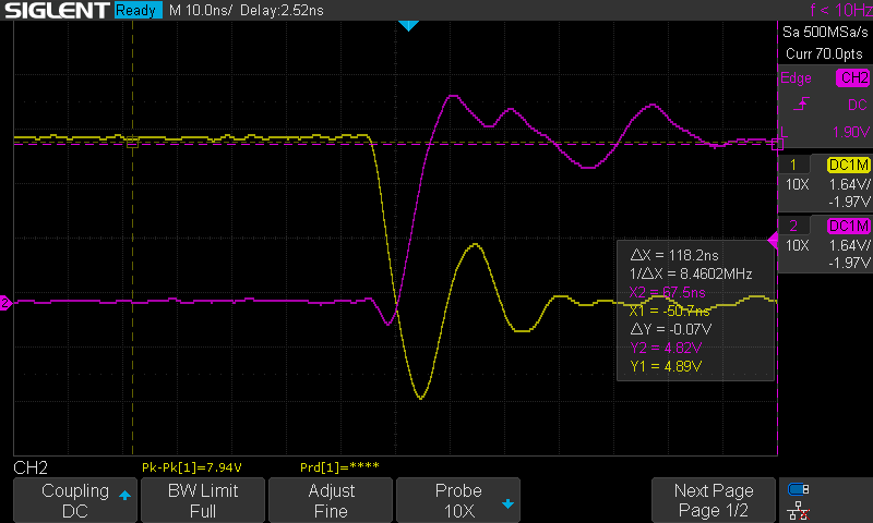
Going from low to high without oscillation:
And another example of oscillation:
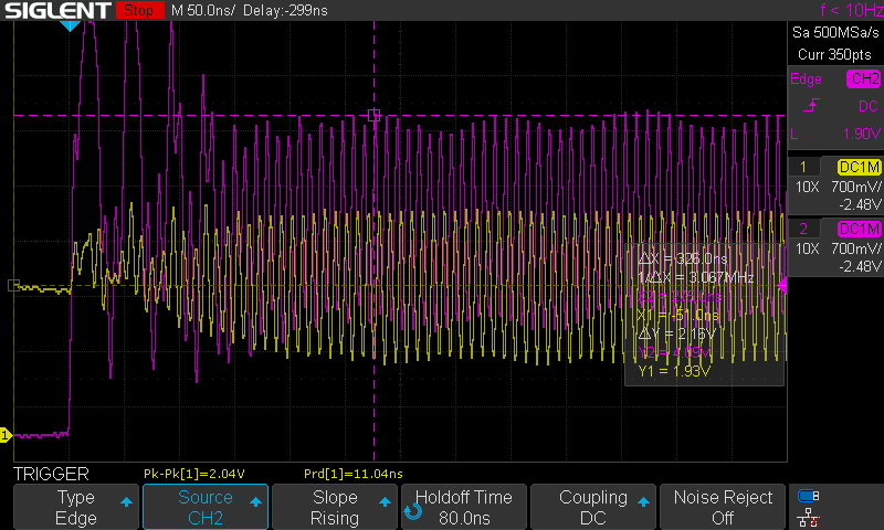
There is some going up and down there too, but it resolves itself.
My question here is really how can the input start oscillating? It is not connected to the output in any other way than the scope probes.
My solution to this has been to attach a capacitor to the input or the output. This dampens the oscillations a bit and so it doesn’t enter that state.
Here is the setup for adding a capacitor the input:
And here is the setup for adding the capacitor to the output:
The capacitor needs to be of a certain capacitance to avoid the oscillation. Through manual binary search, I found that when attached to the input it oscillates at 10pF, it wobbles a bit at 15pF and 18pF, but it never happens at 22pF. When attached to the output it oscillates at 30pF, wobbles at 33pF and it never happens at 39pF.
Here is an output of a switch from high to low with a 22pF on the input:
Here is an output of a switch from high to low with a 39pF on the output:
and a switch from low to high:
The first waveform was a bit longer than it used to on the input, it usually “resolves” faster, but the two results are reproducible. Multiple runs with triggers repeated these two patterns every time.
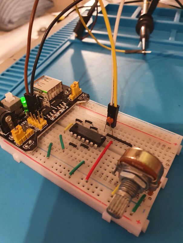
My question for this is why is the switch so much cleaner when the capacitor is on the input, even though it’s smaller than the one we put on the output?Problem 2: No propagation delay when feeding one output into an inputThis is something I tried for fun, which is to connect the output of one of the pins on the IC to another input on the same IC. The setup looks like this:
The oscilloscope setup is the same as last time, so this time the yellow line will be the output of the first Schmitt-trigger inverter and the purple line be the output of the second Schmitt-Trigger inverter.
When I turn it around I get no oscillation like before, but when using a trigger, I see that there is some. Here is for low to high:
and for high to low:
There is some oscillation here, but it dies of quickly. I don’t know why this is, but my real question is:
Why does it seem like they both change levels at the same time?If we look closely:
It looks like they both start changing at the same time. Shouldn’t there be a propagation delay between the input going low and the purple going high?
To test this, I setup another SN74HC14, with identical setup as the first circuit, except that I connected the input of the new SN74HC14 to the output of the first. Here is a picture of the setup:
Now the output from here:

and
and a zoom in:
The zoom in isn’t the best, but from the three pictures I’m not sure if I see any propagation delay at all, here either. Am I just measuring this wrong or? Do I need 3 channels and a faster input to really make this measurement?


