Author Topic: Hard Drive Question  (Read 10934 times)

0 Members and 1 Guest are viewing this topic.

Offline bostonmanTopic starter

  • Super Contributor
  • ***
  • Posts: 2099
  • Country: us
Hard Drive Question
« on: September 29, 2020, 01:21:10 am »
This hard drive is in an Agilent scope and I'm having booting issues (I'm dealing with the issue in the HP forum).

I thought to connect this with an adapter to USB, but Windows isn't seeing the drive. From what I can tell, this is an SSD, but it doesn't have a separate connector for power.

My questions are: what type of drive is this, and do I need to manually connect power to pins?
 

Offline Nominal Animal

  • Super Contributor
  • ***
  • Posts: 6950
  • Country: fi
    • My home page and email address
Re: Hard Drive Question
« Reply #1 on: September 29, 2020, 08:32:48 am »
Looks like a standard 44-pin IDE (parallel ATA) connector to me:


I'd recommend you boot a live Linux (from USB or similar), since it supports much more partition types and file systems than Windows.
 
The following users thanked this post: matthuszagh

Online Halcyon

  • Global Moderator
  • *****
  • Posts: 5975
  • Country: au
Re: Hard Drive Question
« Reply #2 on: September 29, 2020, 09:06:51 am »
Windows may not see the drive if it's not using an NTFS, FAT or exFAT file system. Can you see the physical disk itself in Device Manager or the Disk Management Console?

It is unlikely to be an SSD with an IDE interface, unless it's a form of early flash (such as Compact Flash).
 

Offline Nusa

  • Super Contributor
  • ***
  • Posts: 2417
  • Country: us
Re: Hard Drive Question
« Reply #3 on: September 29, 2020, 10:46:27 am »
Clearly an 44-pin IDE interface, including the key pin. If you want to treat it as an IDE drive, you need a matching IDE interface, including power.

But take the plastic cover off and see what's inside. Bet you the entire box is just a 44 pin IDE to mSATA adapter which allowed Agilent to use an SSD without changing the interface.
https://www.aliexpress.com/item/1005001275289940.html

In that case, of course, the question is whether you have an mSATA adapter to whatever it is you actually have.
 

Offline bostonmanTopic starter

  • Super Contributor
  • ***
  • Posts: 2099
  • Country: us
Re: Hard Drive Question
« Reply #4 on: September 29, 2020, 01:00:20 pm »
This drive was installed in the scope by someone else using a 3.5" (?) IDE ribbon cable to 2.5" adapter.

The adapter has a side connector (see attached picture). The scope only has a tiny two pin power connector that doesn't fit correctly, so the person used hot glue to keep it attached.

My confusion is: a 2.5" to USB interface I'm using to communicate with my PC connects to every pin indicating power is fed from the USB.

My assumption is I need to break out the 5V and GND pins to get power to them.
 

Offline Nominal Animal

  • Super Contributor
  • ***
  • Posts: 6950
  • Country: fi
    • My home page and email address
Re: Hard Drive Question
« Reply #5 on: September 29, 2020, 01:53:24 pm »
The 44-pin IDE (AKA 2.5" IDE) connector has 5V for logic, and 5V for the motor, in the four extra pins.  You can use the USB +5V for these, although it'd be nice if there was some extra filtering (for the logic supply).  It looks like that particular disk does not need it, though (I'd guess SSD's don't).  The side pins in the adapter you have are obviously for the +5V supply, since normal 40-pin IDE cables do not have such a pin.

5V is connected to pins 41 and 42, and ground to 43 and 44 (as well as 2, 19, 22, 24, 26, 30, and 40; the key/missing pin is 20).  If you disconnect your adapter, you can verify these using a DMM, since there is no active logic on the adapter at all.

If you look at the 40-to-44-pin IDE adapters on e.g. fleabay, you'll see that they just break out the +5V pin using a standard PC power MOLEX connector. (The 12V is not used, and is not connected to anything.)  One of those might be preferable, if you can scavenge a 4-pin PC power molex cable, and replace the +5V/GND pair with the connector to the scope.  Beats hot snot, at least.

Forgot to add: the 44-pin IDE connector on the drive indicates it could very well be an adapter and a CF-card inside.  If it is, you can use a multifunction card reader (with CF/CompactFlash support) to read its contents, and duplicate to an actual SATA SSD.  Then, you could use a standard IDE to SATA converter; although you might need a regulated 12V for one. 
« Last Edit: September 29, 2020, 02:11:53 pm by Nominal Animal »
 

Offline bostonmanTopic starter

  • Super Contributor
  • ***
  • Posts: 2099
  • Country: us
Re: Hard Drive Question
« Reply #6 on: September 29, 2020, 02:53:18 pm »
Getting the connector type is a big help.

I assumed it was IDE, but, since the drive doesn't have a separate connector for power, I was confused.

It looks like the USB to drive adapter doesn't provide +5V. I'm uncertain how to connect +5V since the adapter covers all 44 pins.

What seems odd: the drive was warm when connected to the USB adapter, so I sensed it was getting power, however, maybe the data lines were causing the heat and it wasn't getting the +5V it needed to communicate with the PC?
 

Offline bostonmanTopic starter

  • Super Contributor
  • ***
  • Posts: 2099
  • Country: us
Re: Hard Drive Question
« Reply #7 on: October 02, 2020, 02:50:42 am »
Quote
But take the plastic cover off and see what's inside. Bet you the entire box is just a 44 pin IDE to mSATA adapter which allowed Agilent to use an SSD without changing the interface.


I removed the cover and took pictures of the inside. At some point in my life I blinked and suddenly all these new pin outlines and names surfaced. I never came across this type of card, however, after doing some research, I think a USB adapter would be in the Amazon link below.

Is this a safe and correct adapter?

https://www.amazon.com/Adapter-Tanbin-Portable-External-Converter/dp/B075FR3ZD4/ref=asc_df_B075FR3ZD4/?tag=hyprod-20&linkCode=df0&hvadid=241963357402&hvpos=&hvnetw=g&hvrand=15155739965278372800&hvpone=&hvptwo=&hvqmt=&hvdev=c&hvdvcmdl=&hvlocint=&hvlocphy=9001894&hvtargid=pla-452824114242&psc=1


Offline Nominal Animal

  • Super Contributor
  • ***
  • Posts: 6950
  • Country: fi
    • My home page and email address
Re: Hard Drive Question
« Reply #8 on: October 02, 2020, 12:53:04 pm »
Is this a safe and correct adapter?
The type – USB to msata  – is correct, but whether that particular one is safe, I have no idea.  :-[

My local reputable seller (Verkkokauppa.com) sells a very similar device made by DeLock.  As in looks exactly the same.  Perhaps Tanbin is the original manufacturer, or they both have their roots in the same example design in an appnote of the controller chip, or one is a clone.

Based on the reviews and the similarity to the delock one, my personal opinion is that it should work fine.  The thing I would do, is monitor the temperature of the voltage regulator – biggest component on the board – in case it gets too hot to touch.

(I use a FrankenModem, a Huawei ME909s-120, connected to a Linux SBC via an "USB-WWAN" adapter, which looks very much the same.  The adapter is "dumb", having only a 5V to 3.3V supply, some supply bypass capacitors, and a SIM card socket.  I got about six of those adapters for a few bucks each, until I got one that uses a DC-DC converter.  In my use case (large antenna, long distances), the modem needs 200mA on average, maybe 500mA averaged peak I guess (I only used a cheap USB power meter with maybe 5Hz update rate), so a linear regulator puts out half a watt to a watt of heat, with only about a quarter of a square inch of copper – and gets too hot for continuous running.  The DC-DC one stays cool.  I do believe the main issue on those USB-mSATA adapters is also the voltage regulator, as the rest of the circuit is obviously straight from the datasheet/appnote/design example/recommended layout.)
« Last Edit: October 02, 2020, 12:58:20 pm by Nominal Animal »
 

Offline bostonmanTopic starter

  • Super Contributor
  • ***
  • Posts: 2099
  • Country: us
Re: Hard Drive Question
« Reply #9 on: October 02, 2020, 02:41:54 pm »
Getting back to the drive itself, is this considered an SSD drive since it has a mSATA board inside?

Since +5V comes in on pins 41 and 42, if I were to stick this in a laptop or PC, would it get the +5V or is this connector different than a standard 44 pin drive?
 

Offline Nominal Animal

  • Super Contributor
  • ***
  • Posts: 6950
  • Country: fi
    • My home page and email address
Re: Hard Drive Question
« Reply #10 on: October 02, 2020, 03:00:22 pm »
mSATA connector is physically the same as mini-PCIe connector, but electrically totally different.  The pinout is here; more details at Wikipedia.

Notably, it has two differential signal pairs, a TWI (I2C) line, sleep pin, drive activity led pin, presence detection pin, five pins with 3.3V power, and thirteen ground pins; the rest of the pins are not connected at all.  The 3.3V DC power is the only power supplied to the mSATA device.

(In other words, mSATA == SATA data cable + TWI + sleep pin + drive LED + lots of 3.3V power + ground.  Those differential signal pairs ARE the SATA differential signals, and go directly to the SATA controller.)

(This is also why there is always a voltage regulator or a 5V-to-3.3V DC-DC converter on these USB adaptors.  The situation with USB-WWAN adaptors is similar, except there the pinout is different -- the mini-PCIe connector is the same; the WWANs run on 3.3V.  That's why I said they're quite similar, and emphasized the need to check the voltage regulator temperature.)
« Last Edit: October 02, 2020, 03:03:48 pm by Nominal Animal »
 

Offline Nominal Animal

  • Super Contributor
  • ***
  • Posts: 6950
  • Country: fi
    • My home page and email address
Re: Hard Drive Question
« Reply #11 on: October 03, 2020, 11:21:58 am »
Sorry, didn't realize I didn't actually answer the question you (bostonman) asked.

Yes, it is an SSD drive with an mSATA connector.

It is housed in an enclosure with an active adapter, with external interface 44-pin IDE (parallel-ATA).  That interface is supplied with +5V from somewhere in the 'scope, and the IDE (= PATA/parallel-ATA) connected to the scope.

You can take just the mSATA SSD drive, and connect to a laptop, or even a computer via a suitable adapter.  (Such adapters vary from bare boards, to cable adapters, to external enclosures.)  No matter which way you connect the drive, its data should be accessible, as long as your OS supports the partition formats.  (Which was why I recommended using Linux, as you can basically mount anything and everything; and even if you can't, you can clone the drive to another, or back it up.)

The important thing to realize is that the small enclosure you have, is an active adapter, for connecting an mSATA drive to a host with an IDE interface.

If you wanted to replace the drive, you could use a "IDE to SATA" or "PATA to SATA" adapter, or even an "IDE to M.2" adapter (if you wanted to switch to a M.2 SSD).  The only "problem" is to obtain the 5V needed; you need to locate a source in the 'scope that provides the 5V needed.  (Also, some IDE to SATA/PATA to SATA adapters might need 12V, as they directly convert it to 3.3V, and do not actually use the 5V for anything.  The "IDE to M.2" adapters only need 5V, and internally have both active logic, and a 5V to 3.3V conversion.)
« Last Edit: October 03, 2020, 11:24:09 am by Nominal Animal »
 

Offline bostonmanTopic starter

  • Super Contributor
  • ***
  • Posts: 2099
  • Country: us
Re: Hard Drive Question
« Reply #12 on: October 03, 2020, 01:19:29 pm »
How would I know not to connect this to a standard IDE cable since the connector size is the same?

Currently this drive is in an Agilent oscilloscope. The original 3.5" (?) was replaced with this 2.5" SSD version. Initially the scope was loading (with Win95 or Win98), but, when I touched the 3.5" to 2.5" adapter (which has only 44 pins and a 2 pin power connector hanging off), the system stopped loading Windows. The power connector in the scope and the one on the adapter are different, so the person used hot glue to keep it from slipping off.

I'm involved with the HP group on trying to solve the booting issue, but I'm wondering whether this drive is incompatible since it's an old IDE cable with a modern SSD pin configuration.
 

Offline Nominal Animal

  • Super Contributor
  • ***
  • Posts: 6950
  • Country: fi
    • My home page and email address
Re: Hard Drive Question
« Reply #13 on: October 03, 2020, 01:28:04 pm »
Ah, now I understand.  Consider the assembly:


The blue board with the SanDisk sticker, fastened with two screws, is the SanDisk mSATA SSD, model SDSA4DH-016G.

The green board, with mSATA2IDE25VAO silkscreened on it, is an active adapter, that allows connecting an mSATA drive to an IDE/Parallel ATA host (computer/scope).

If you unscrew the two screws on the blue board, you can remove the mSATA SSD from the mSATA2IDE adapter, and use it as a normal mSATA disk.

The adapter contains active logic.  It talks to the host computer/scope via parallel ATA (PATA = IDE), and to the drive via SATA.  (It just happens to use a mSATA connector on the drive side.)
 

Offline bostonmanTopic starter

  • Super Contributor
  • ***
  • Posts: 2099
  • Country: us
Re: Hard Drive Question
« Reply #14 on: October 03, 2020, 01:34:36 pm »
Ah okay.

My plan is to image this drive. Initially I attempted to use my USB to 44 pin with separate Molex (?) power connector, however, I can't get power to the drive since it only has 44 pins.

Now I'm thinking to buy a mSATA to USB adapter in order to image it. Because I can't find the Agilent software for the scope (I guess it no longer exists), I need to preserve this drive. I don't know why Windows is no longer loading, but I'd like to start by imaging this in hopes a new drive will work.

I'm not asking for help with the scope as I'd feel guilty double dipping on help since I'm already involved on the HP site, but just trying to understand this drive (and all the style connectors).
 

Offline Nominal Animal

  • Super Contributor
  • ***
  • Posts: 6950
  • Country: fi
    • My home page and email address
Re: Hard Drive Question
« Reply #15 on: October 03, 2020, 02:54:49 pm »
Now I'm thinking to buy a mSATA to USB adapter in order to image it.
I would do that too.  Like I linked to earlier, I'd use either the DeLock USB-to-mSATA adapter (as I can get one from a reputable brick-and-mortar store nearby) or a similar one from eBay/Amazon/etc. for imaging.

I'm not asking for help with the scope as I'd feel guilty double dipping on help since I'm already involved on the HP site, but just trying to understand this drive (and all the style connectors).
It would help to know what kind of power connector the scope has.  I assume it is the standard 4-pin PC power MOLEX connector, with two grounds in the center, and +5V and +12V on the outer pins?

What I would do – which means no guarantees! – is to use an bidirectional IDE-to-SATA converter board, like this DeLock one.  You either plug it in directly to the IDE connector on the scope, or use a 40-pin IDE cable and a male-male adapter.  For power, you connect a PC MOLEX FDD power cable (4-pin MOLEX to 4-pin floppy drive power connector) between the MOLEX connector on the scope and the 4-pin FDD power on the adapter.  Then, you use a standard SATA data cable, and a standard SATA power cable, to connect to a SATA drive.  (Both cables are male-male, and very common.)
For the drive, I'd use WD Green 120G SSD drive (WDS120G2G0A); cheap, but reasonably reliable (3 year limited warranty).  Total cost would be about $50-$60 or so.

Note that a lot of the IDE-SATA adapters are for connecting an IDE drive to a SATA host.  Your use case is the opposite.  Because the adapter needs active logic, not all adapters are suited for your use case.  That's why I'd pick a bidirectional one.

To reiterate: I am NOT saying that these DeLock products are "best" in any way.  They are just the ones I can find in reputable stores nearby; stores where I know from experience the warranty procedures work. (Both are also produced in China, so clones or un-badged OEM versions should not be difficult to find on Amazon/eBay/etc.)  Consider my links as EXAMPLES of products I'd be willing to buy in your situation, not endorsements or anything.
« Last Edit: October 03, 2020, 03:03:23 pm by Nominal Animal »
 

Offline Nominal Animal

  • Super Contributor
  • ***
  • Posts: 6950
  • Country: fi
    • My home page and email address
Re: Hard Drive Question
« Reply #16 on: October 04, 2020, 11:23:28 pm »
Another option is to use an IDE-to-CompactFlash adapter, like this one.  It connects directly to the IDE connector on the 'scope, and power is supplied from the 4-pin Molex on the scope to the adapter (with a floppy disk power connector).
In my part of the world, it costs about 15 € or USD $18, in Sept. 2020.

16GB or larger CompactFlash cards cost here from 30€ up.  As I mentioned, I like SanDisk ones, and the 32GB Extreme Pro costs here 60-70€ (70-80 USD).  SanDisk/Western Digital gives it a lifetime/30-year warranty, depending on where you live.  It should have over 100 Mbytes/sec read and write speeds; at least 65 Mbytes/sec sustained write speed.  So, not nearly as fast as SSDs, but might be okay for scope use.

Many USB multi-card readers support CF cards, so imaging/backing the CF card for future use if it breaks should be very simple.  Since a lot of cameras still use CF cards, I'd wager they'll stay available for the next decade or so. 
 

Offline bostonmanTopic starter

  • Super Contributor
  • ***
  • Posts: 2099
  • Country: us
Re: Hard Drive Question
« Reply #17 on: October 05, 2020, 12:09:00 am »
Maybe the scope model number will help, but I think it's been modified. It's a Agilent 54831M.

I don't see any Molex connectors. It has a 3.5" and CD ROM, however, I don't see any power connectors for them and assume they once were powered.

Having said this, you can see in the attached pictures the small two pin power connector going to the adapter. A second unused one is floating around, however, those are the only two connectors floating around.


Offline Nominal Animal

  • Super Contributor
  • ***
  • Posts: 6950
  • Country: fi
    • My home page and email address
Re: Hard Drive Question
« Reply #18 on: October 05, 2020, 12:25:09 am »
The black and red wire hot-snotted to the adapter should go into the power supply, not to the motherboard.  I am wondering whether the black and red wire form a cable (with a connector on the power supply end too), or if it is directly connected to the power supply.  In either case, it *should* be +5V and ground.  Could you check?
 

Offline bostonmanTopic starter

  • Super Contributor
  • ***
  • Posts: 2099
  • Country: us
Re: Hard Drive Question
« Reply #19 on: October 05, 2020, 12:28:42 am »
I'll measure the voltage tomorrow, but it goes to (what I believe to be) the power supply. It's the one in the picture with the large Molex (?) connector.
 

Offline Nominal Animal

  • Super Contributor
  • ***
  • Posts: 6950
  • Country: fi
    • My home page and email address
Re: Hard Drive Question
« Reply #20 on: October 05, 2020, 12:45:42 am »
Yup, the wires connected to the large molex connector on the motherboard, are connected to the power supply.

The big molex does look like a standard ATX motherboard power supply connector (pinout) with some pins omitted, but don't assume it has that pinout without checking!
 

Offline bostonmanTopic starter

  • Super Contributor
  • ***
  • Posts: 2099
  • Country: us
Re: Hard Drive Question
« Reply #21 on: October 07, 2020, 12:58:13 am »
The two small connectors have 5.1V on them.

I don't know the connector type, but I'm uncertain why they are used. It's only a two-pin (black and red) connector. The scope doesn't have any power connectors for the CD-ROM, or 3.5" floppy; nor does it have any Molex connectors for SATA or old 3.5" drives.

The 3.5" to 2.5" adapter only has 44 pins with a connector on the side. It doesn't mate with the one in the scope, so it was shoved in and held in place with hot glue.

At the moment, the scope is no longer loading the OS (as I mentioned, I'm dealing with this issue in the HP newsgroup), but moving forward, I'd like to put a "normal" drive in this scope. For that, I imagine I'll need to figure how how to tap off the Molex power connector.

I don't understand why it doesn't have a SATA or Molex for a hard drive since this scope once had (I believe) a 3.5" drive. Someone must have went through the trouble of cutting wires.

Is it possible the motherboard was upgraded and drive power cables should be coming off it?
 

Offline Nominal Animal

  • Super Contributor
  • ***
  • Posts: 6950
  • Country: fi
    • My home page and email address
Re: Hard Drive Question
« Reply #22 on: October 08, 2020, 11:08:13 pm »
The two small connectors have 5.1V on them.
They provide the 5V supply to the drive, then.  Good, that means that you only need to change the connector to provide the power to a IDE-to-SATA or IDE-to-CompactFlash adapter.

If you compare to a standard PC peripheral power 4-pin Molex connector or the FDD power connector, only the red (+5V) and black (GND) wires are used:

The yellow is for +12V, and all black wires are ground.  When the +12V is omitted, the ground next to it is usually omitted too.
The connectors on the left are the ones that connect to devices/adapters.

The 3.5" to 2.5" adapter only has 44 pins with a connector on the side. It doesn't mate with the one in the scope, so it was shoved in and held in place with hot glue.
Yes.  The 40 pins are the same as in an IDE/PATA connector (on the scope), and the extra four pins are two grounds and two +5V power.  The 44-pin IDE/PATA connector provides +5V to the device, and there is no separate power connector.

If you look at the device-side pinout of the 44-pin IDE/PATA connector,

then the two outermost extra pins are ground, and the next two pins +5V.

Instead of an adapter board (from 40-pin IDE and power Molex to 44-pin IDE/PATA), you could use a cable:
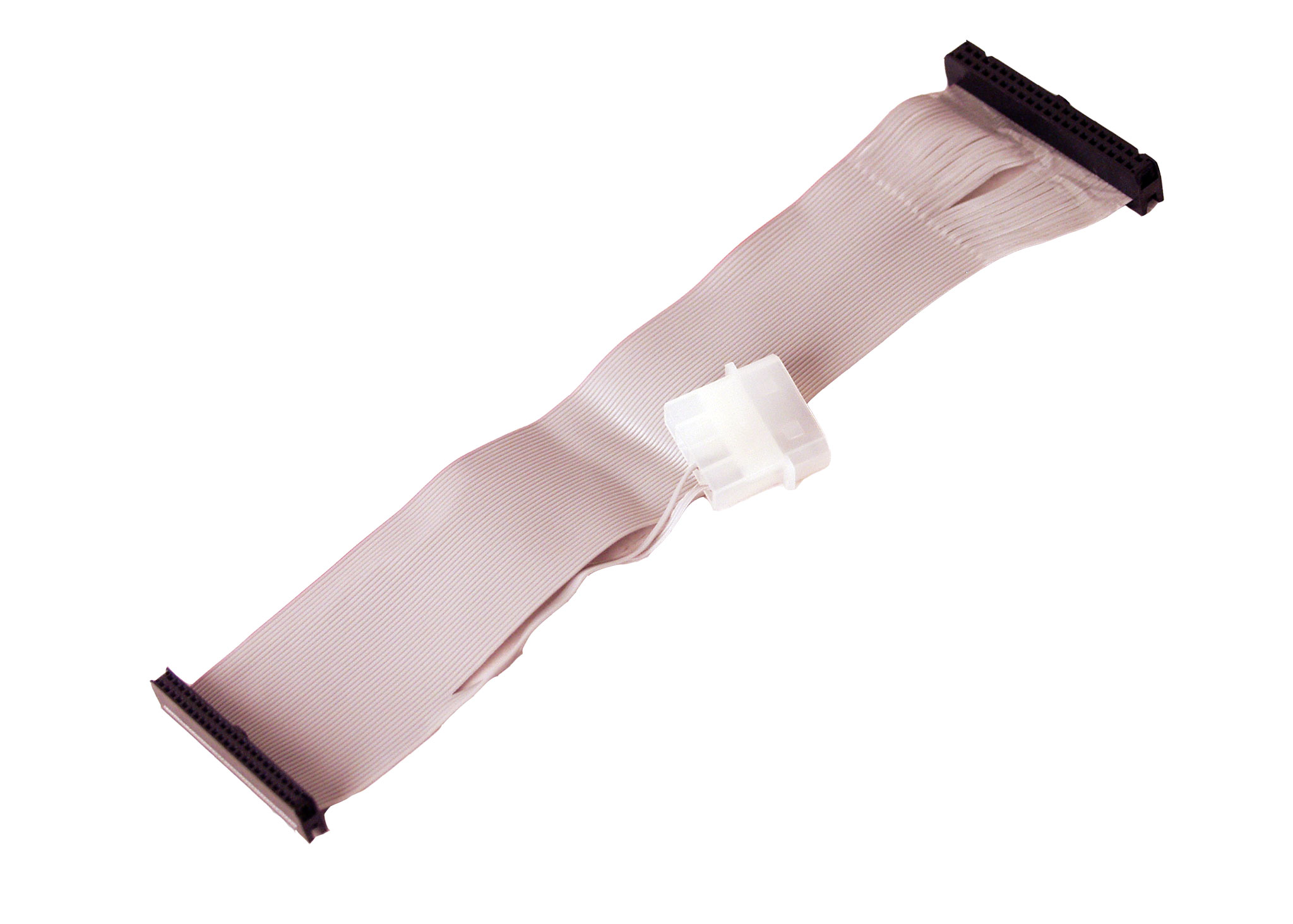
On the Molex connector, the outer pin is the +5V, and the inner pin is ground.

At the moment, the scope is no longer loading the OS (as I mentioned, I'm dealing with this issue in the HP newsgroup), but moving forward, I'd like to put a "normal" drive in this scope. For that, I imagine I'll need to figure how how to tap off the Molex power connector.
Since there is no +12V available, you're limited to 2.5" drives (both IDE and SATA 2.5" drives only use the +5V supply) and solid-state drive adapters to SATA SSD, SATA M.2 NGFF, CompactFlash, etc.

I don't understand why it doesn't have a SATA or Molex for a hard drive since this scope once had (I believe) a 3.5" drive. Someone must have went through the trouble of cutting wires.
Yes, I believe so, too.

I am not 100% sure if the bidirectional IDE-to-SATA adapters need +12V or not, so if you intend to get one, do check if it works without +12V first (noting that you should only use 2.5" drives that do not use the +12V).  I believe the adapters only pass +12V through and use the +5V for internal stuff, but the fact that many of them have two voltage regulators on them makes me wonder.

There were even in the olden days when IDE/PATA was used, drives that only needed +5V.  It is possible that the connector you now have was originally a female 4-pin Molex with only two pins connected (+5V on the edge, and GND on the inner pin), and someone just cut it off, put that new connector on, and hot-snotted it in place.
Or perhaps the connector is original, and they just misplaced the adapter (from that to 4-pin molex or 4-pin FDD connector; possibly an Y cable).

Is it possible the motherboard was upgraded and drive power cables should be coming off it?
It is technically possible, but weirder than a grill in an ice cream shop.  I've never seen a motherboard with peripheral power connectors; those have thus far always come straight from the power supply.


Since you are having problems with the current adapter, I would recommend replacing it with a cable. (You see, after looking into this, I suspect the adapter is broken, one of the solder connections being broken – it is a common complaint on the IDE adapters.  The simple cable approach is more robust.)
For example, this one from an US fleabay seller.  Connect the two red wires to the +5V off the scope supply, and the black wire to ground.  (I would replace the scope +5V connector with a molex one, scavenging an existing PC peripheral power cable (Y cables are a good source if you don't already have them), soldering the wires together (instead of de/re-pinning the connector).

To replace the existing drive and adapter, I would use the above, and a 44-pin IDE to slimline-SATA adapter, for example this one also from an US fleabay seller.  In other words, this is connected to the 44-pin cable above, and gets its power (5V) from the extra pins; no separate power cable.  Again, I like the WD Green 120G and 240G SSD SATA drives, so that's what I'd use for the SSD drive itself.  Your choice, though.

The SATA connector on these kind of adapters is notorious for breaking; they really cannot handle many detach-attach cycles at all.  If you need to, get a slimline SATA extension cable (like this one from the same US fleabay seller as the other cable), and leave one end always connected to the adapter.
This way, the adapter is basically "hanging in the air", so you might have to attach it to the scope chassis somehow, to stop it from shorting out anywhere.  The adapter does not have any convenient attachment points, so the best option is likely to get a small plastic box for it, and saw/file room for the two cables on the long sides between the box and its lid.  Or, if you have a 3D printer, print a small enclosure with it, with lots of holes in it for keeping it cool, in case it gets hottish.
« Last Edit: October 08, 2020, 11:10:58 pm by Nominal Animal »


Share me

Digg  Facebook  SlashDot  Delicious  Technorati  Twitter  Google  Yahoo
Smf