I nearly forgot, I have a japanese battery charger that I mistakenly plugs on main 230V without really checking if it was an automatique switchable one, and in fact it was working (the output was correct) unless a big bang occurred somewhere, which was of course inside the charger, a cap inside just didn't liked to be plugged on 230V.
So as I wanted to repair this board and see if I could make it working on european main voltage without major changes, aka just change some component values, I started to look at the component and try to make a schematic of it. My main problem was that there is an IC where I can't find any data sheet,
I managed from the logo on it that the original company (Matsushita) was bought by Panasonic, and try to find on there website a reference for this component, I found that it exist, but there were no documentation on it. I filled a ticket requesting for the data sheet, at some point the ticket changed to
[Q&A Destination After Changing]
Interface & Communication / Analog / DC-DC Regulator / RF
Field : Analog ICs
Detail Field : Other Analog ICs
and I finally get a "old component, we don't give data sheet for old components"... Thanks panasonic.
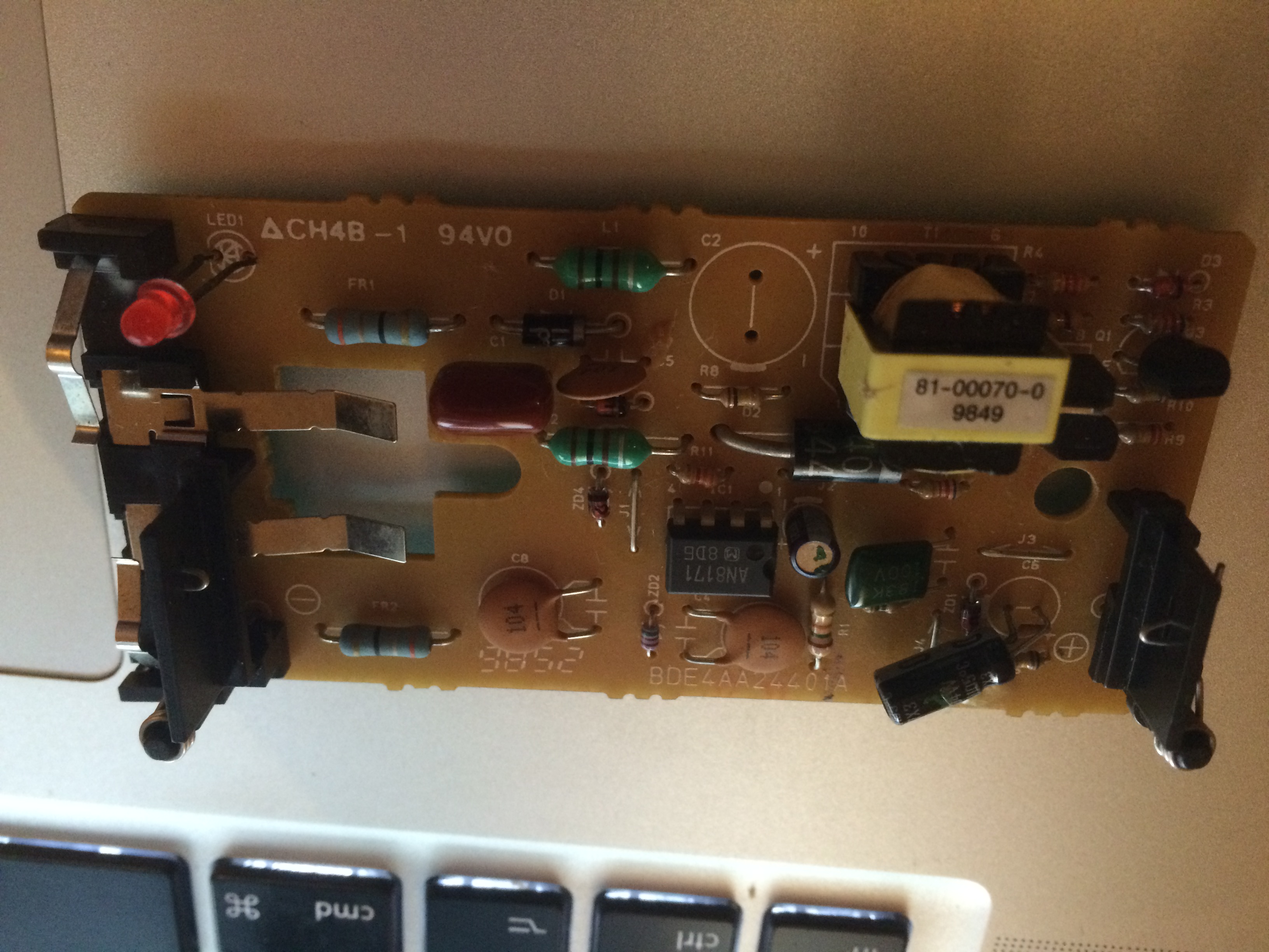
So here is the board :
Front:
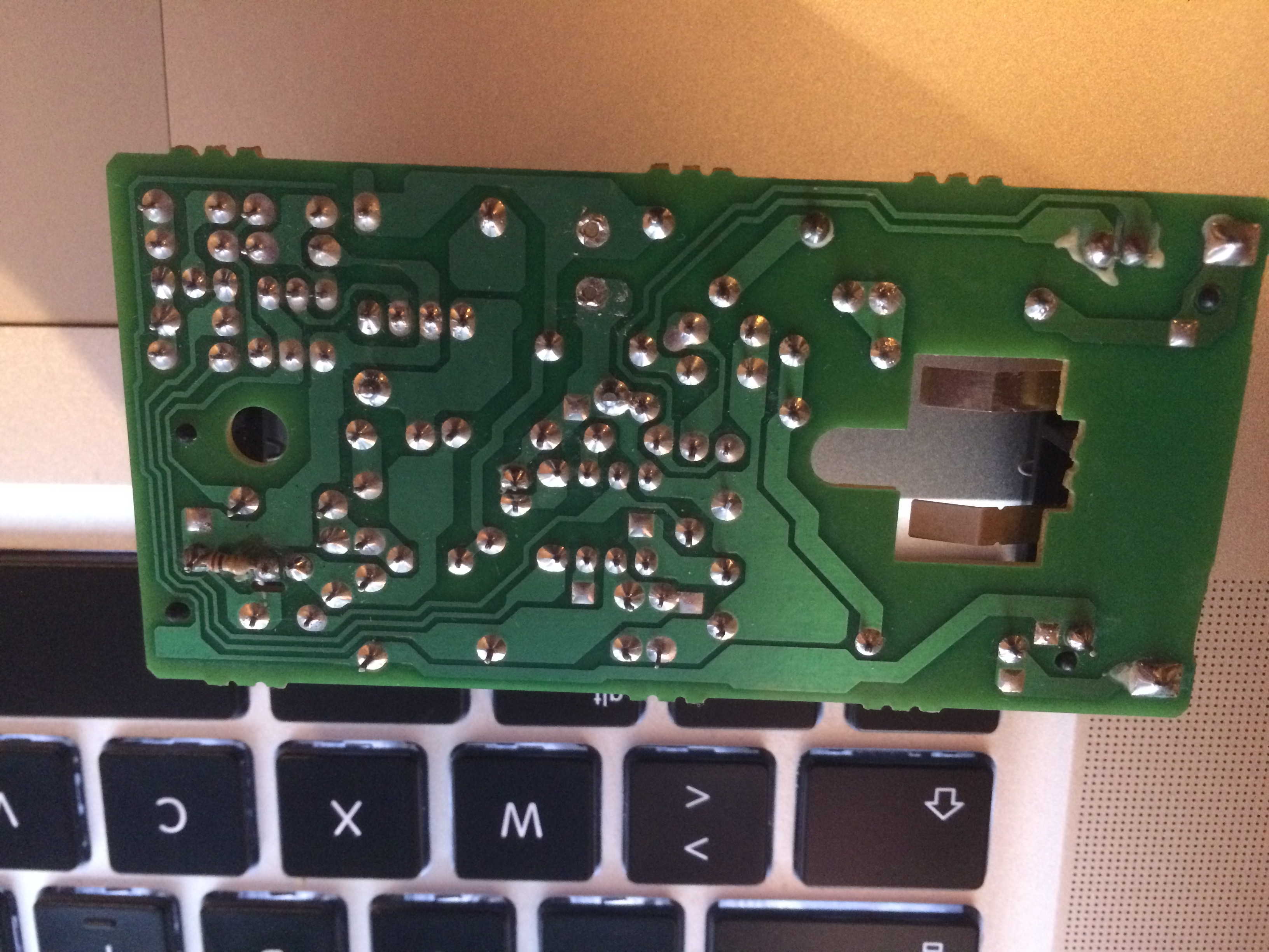
Back:
And the chip is the AN8171
If anyone have information about the chip, I would be thanksful

I suspect that this is mainly a controller for the battery change or something related to the AC to DC converter, I'm not sure.
(I know that if a Dave will look at the PCB for this charger he will just get a heart attack, there design is quite strange, pads or track that does nowhere, some clearance between main and low voltage are just... really tiny

And it was made by a bit japanese company, and not a small chinese one..
By the way, the FR1/FR2 are high chance to be some sort of fuse resistors, but the value, if they follow the standard resistor colour band seems strange to me (Orange, White, Black Silver if I'm correct)
I may create a topic about this specific device if some people are interested, I'm trying to find the schematics I've done at that time, but it's currently nowhere to be found, anyway I know that most of it around the transformer is false


