Author Topic: "Veritasium" (YT) - "The Big Misconception About Electricity" ?  (Read 263958 times)

0 Members and 8 Guests are viewing this topic.

Offline aetherist

  • Frequent Contributor
  • **
  • !
  • Posts: 621
  • Country: au
  • The aether will return. It never left.
Re: "Veritasium" (YT) - "The Big Misconception About Electricity" ?
« Reply #1950 on: May 10, 2022, 09:33:53 pm »
With transmission lines, especially those of substantial length, the voltage and current are local, and don't include uncontrolled long wires outside the measurement.
Ideally, one defines a plane, perpendicular to the long direction of the coaxial cable (in this example) and the ideal voltage probe/oscilloscope measures the voltage from center to outer conductors in that plane, and the ideal current probe measures the current through the inner conductor passing through that plane.
Practical oscilloscope and current probes try to emulate that ideal situation.
When the diameter of the coax (again, in this example) becomes too large at the time scale of the measurement, we are crossing into waveguide territory, where we concentrate on the fields in the interior of the guide.  Note that waveguides can be built with dielectric walls instead of conductive walls, with well-defined (in conventional electrodynamic theory) results similar to conductive guides, with the possibility of having a large DC (or lower-frequency than the waves) voltage from one end to the other.  Similarly, if the interior of the waveguide is evacuated, one can run current in the form of electron or ion beams down the length of the guide, which will interact with the high-frequency fields.  As mentioned in someone else's textbook citation, at the frequencies where waveguides are common, the skin depth in the metal walls is very small, and the energy is transported mainly in the traveling wave down the guide.  With a bad termination, or a resonant cavity, energy can be stored in the standing wave.
There is a large literature and industrial history of both waveguides in general and particle accelerators in particular.  Again, they both work.
When Heaviside made his huge breakthrough (realizing that adding lumped inductors in series with the telegraph lines improved their bandwidth), he may have used the telegraph system grounding as the return (bandwidth is not so high with manual Morse code).  When AT&T successfully adopted his method to trunk telephone lines, they used twisted-pair transmission lines (balanced with respect to ground).
By the way, with respect to the outer insulation (jacket) on coaxial cables.  I have used precision coaxial cables, some of which had armored jackets to prevent damage, and coaxial cables with various dielectrics (usually PE or PTFE), and various jackets (usually PVC), but also "semi-rigid" coaxial cables, where the outer conductor is essentially a copper tube, with no outer insulation.  Careful use of these semi-rigid cables requires proper tooling for making bends, so as not to destroy the inner geometry.  See  https://www.pasternack.com/pages/Featured_Products/hand-formable-semi-rigid-cable-assemblies-up-to-18-ghz-new-from-pasternack.html?utm_campaign=usa_cable_assemblies&keyword=semi-rigid%20coaxial%20cable%20assemblies&gclid=eaiaiqobchmi2dv1-dzv9wivshrnch1uia-oeaayasaaegkoypd_bwe   for such assemblies available with or without outer insulating jacket.  Again, they work the same either way.
Waveguides are another area where i know little, but i can smell a 2nd Nobel medallion.
Wires are a guide for electricity (elektons, ie photons). And wires can carry a flow of free surface electrons & drifting internal elektrons.
Waveguides are a guide for em radiation (radio waves)(radar).
It seems that em radiation (my photaenos) reflects off surfaces a bit like free photons (eg light) reflect.
I am worried about the term wave. E×H has no wave, it is a slab, all of the fancy perpendicular sinusoidal models are wrong.
However, the E×H can have a manmade wave, & hence yes the waveguide is a waveguide.
Wires carry photons, waveguides carry photaenos.
Naming em radiation photaenos aintgonnagetme a Nobel. I have to be patient.

Anyhow, i daresay that a waveguide has a Poynting Field inside.  But here again i say that the Poynting Field duznt carry energy, it merely describes what is inside the waveguide. On the other hand i think that if we say that the Poynting Field carries the energy inside a waveguide then that kind of notion is fairly harmless, i don’t see it leading to a catastrophe down the track.

I suppose that i am ok with saying that in the Veritasium-X it is the Poynting Field that gives the induction that lights the bulb at  3.3 ns, but i aint ok with saying that it is the Poynting Field that carries the main electrical energy.
« Last Edit: April 29, 2023, 05:50:32 am by aetherist »
 

Offline TimFox

  • Super Contributor
  • ***
  • Posts: 8663
  • Country: us
  • Retired, now restoring antique test equipment
Re: "Veritasium" (YT) - "The Big Misconception About Electricity" ?
« Reply #1951 on: May 10, 2022, 09:52:45 pm »
"I am worried about the term wave. E×H has no wave, it is a slab, all of the fancy perpendicular sinusoidal models are wrong."

What evidence do you have for the assertion that the fancy perpendicular sinusoidal models are wrong? 
The fancy perpendicular sinusoidal models work well with traveling waves down waveguides and radiated waves propagating away from antennae.
Popular modes for waveguides are TE (transverse electric, where the E field component in the longitudinal direction of propagation is zero) and TM (transverse magnetic, the H component in the direction of proagation is zero.)
Arbitrary waves propagating in the longitudinal direction are superpositions of TE and TM, under normal conditions, and the transverse components of (time-dependent) E and H vectors are everywhere mutually perpendicular.
At this point, things get messy, and I don't claim expertise.  Please refer to the standard textbooks on waveguides, and remember that WWII was won through use of radar, waveguides, magnetrons, and klystrons.
The finite conductivity of the walls in rectangular cross-section waveguides is a source of attenuation (loss) as energy propagates  by the sinusoidal fields down the guide.  When you see the mathematical equations, you will notice a spatial dependence in the transverse (cross-section) directions, and a sinusoidal time dependence down the longitudinal direction, with loss also in the longitudinal direction.
There is a cut-off frequency, below which the waves cannot propagate down a rectangular guide, which is why these rectangular pipes are used in the microwave frequency regime. 
All of this stuff in the textbooks follows directly from Maxwell's equations.  I admit that the mathematics is complicated.
« Last Edit: May 10, 2022, 10:07:42 pm by TimFox »
 

Offline aetherist

  • Frequent Contributor
  • **
  • !
  • Posts: 621
  • Country: au
  • The aether will return. It never left.
Re: "Veritasium" (YT) - "The Big Misconception About Electricity" ?
« Reply #1952 on: May 10, 2022, 10:25:58 pm »
"I am worried about the term wave. E×H has no wave, it is a slab, all of the fancy perpendicular sinusoidal models are wrong."

What evidence do you have for the assertion that the fancy perpendicular sinusoidal models are wrong? 
The fancy perpendicular sinusoidal models work well with traveling waves down waveguides and radiated waves propagating away from antennae.
Popular modes for waveguides are TE (transverse electric, where the E field component in the longitudinal direction of propagation is zero) and TM (transverse magnetic, the H component in the direction of propagation is zero.)
Arbitrary waves propagating in the longitudinal direction are superpositions of TE and TM, under normal conditions, and the transverse components of (time-dependent) E and H vectors are everywhere mutually perpendicular.
At this point, things get messy, and I don't claim expertise.  Please refer to the standard textbooks on waveguides, and remember that WWII was won through use of radar, waveguides, magnetrons, and klystrons.
The finite conductivity of the walls in rectangular cross-section waveguides is a source of attenuation (loss) as energy propagates  by the sinusoidal fields down the guide.  When you see the mathematical equations, you will notice a spatial dependence in the transverse (cross-section) directions, and a sinusoidal time dependence down the longitudinal direction, with loss also in the longitudinal direction.
There is a cut-off frequency, below which the waves cannot propagate down a rectangular guide, which is why these rectangular pipes are used in the microwave frequency regime.
Radar etc waves are manmade waves. They can be made to be sinusoidal or any shape we like. They are not the same animal as (non-manmade)(natural) Hertzian waves, which (if they existed)(which they don’t) would be sinusoidal all the time.

E and H are always perpendicular. In every theory.
They are perpendicular in Heaviside's transverse electromagnetic slab of energy current which makes his electric current (Heaviside is wrong)(electricity is my elektons, which emit his em slab).
They are perpendicular in the silly Hertzian rolling E by H by E theory.

There is no rolling E by H by E.  The E & the H always go together, equal at all times.
However, if two H fields negate then we have a nett pure charge field.
If two E fields negate then we have a nett pure magnetic field.

Papers written by Ionel Dinu.  https://www.gsjournal.net/Science-Journals-Papers/Author/111/Ionel,%20Dinu

Trouble with Maxwell's Electromagnetic Theory : Can Fields Induce Other Fields In Vacuum?
https://www.gsjournal.net/Science-Journals/Research%20Papers-Mechanics%20/%20Electrodynamics/Download/4219
Abstract -- The purpose of this article is to point out that Maxwell’s electromagnetic theory, believed by the majority of scientists a fundamental theory of physics, is in fact built on an unsupported assumption and on a faulty method of theoretical investigation.  The result is that the whole theory cannot be considered reliable, nor its conclusions accurate descriptions of reality. In this work it is called into question whether radio waves (and light) travelling in vacuum, are indeed composed of mutually inducing electric & magnetic fields.

Radio Waves – Part IV : On the false Electric Waves of delusional Heinrich Hertz.
https://www.gsjournal.net/Science-Journals/Essays-Mechanics%20/%20Electrodynamics/Download/6248
Abstract -- After writing a paper critical to Maxwell’s electromagnetic theory, it is only natural to continue with an article critical to Hertz’s work. This is because every physics textbook today claims that Hertz demonstrated experimentally Maxwell’s theory. This claim amounts to saying that Hertz demonstrated experimentally that radio waves and light are electromagnetic, i.e. that they are made up of entangled electric and magnetic fields that oscillate and induce one another. In this work it will be shown that Hertz’s claim of having verified experimentally Maxwell’s theory is an exaggeration simply not true. Although Hertz did confirm the existence of a certain wave propagating in air, it cannot be said that his verification that the waves were composed of magnetic and electric oscillations is correct. And Hertz explicitly stated that he did not offer a direct verification that light itself is electromagnetic. I only wish more physicists read Hertz’s works before believing Maxwell’s theory or that it has been confirmed experimentally through Hertz’s works or otherwise.

Radio Waves – Part II.   
https://www.gsjournal.net/Science-Journals/Research%20Papers-Mechanics%20/%20Electrodynamics/Download/4892
Abstract -- In Part I of this series on Radio Waves, I have tried to show that Maxwell’s theory of electromagnetic waves is untenable because electric fields cannot exist in vacuum where there are no electric charges to produce them and because experiments have yet to prove that electric fields can be produced in vacuum by changing magnetic fields. My aim was to show that a new theory of radio waves is needed since that based on Maxwell’s theory of electromagnetic waves claiming that a radio wave travelling in vacuum consists of oscillating electric and magnetic fields mutually inducing one another is not supported by experiments, being based on assumptions and mathematical manipulations.
Comments received from interested readers prompted me to offer further arguments against Maxwell’s theory and this led to an extended version of the same paper titled “Trouble with Maxwell’s Electromagnetic Theory: Can Fields Induce Other Fields in Vacuum?”.  In this article I return to my original aim when I began this series on Radio Waves and I will try to show what I think radio waves really are and how are they produced in an antenna.
« Last Edit: April 29, 2023, 05:48:56 am by aetherist »
 

Online IanB

  • Super Contributor
  • ***
  • Posts: 12427
  • Country: us
Re: "Veritasium" (YT) - "The Big Misconception About Electricity" ?
« Reply #1953 on: May 11, 2022, 05:51:18 am »
This is because every physics textbook today claims that Hertz demonstrated experimentally Maxwell’s theory.

This is a general problem that comes up over and over again. Learning, understanding and education is not about reading textbooks as received wisdom and believing what they say. That is not science, that is religion.

Nobody knows what electrons, photons, electric fields, magnetic fields or electromagnetic radiation really are, and probably nobody can know. It is a pointless subject to argue about and serves no purpose.

What I do know is that people can design smartphones and computers and many other devices using established models of the world, and those devices work as intended. If our models were wrong, then all the engineers trying to design things would get very frustrated.

The way to make headway in a debate such as this is not to write lots of words and somehow think they convey meaning, because words are just words. You can make them say anything you like, but to what purpose? The way to make progress is to show that when people try to design computers, or telecommunications equipment, or silicon chips, that they fail, and that their designs do not work. Once you can show that, then you have evidence to claim that our model of the world is wrong and that we need new physics.
 

Offline Berni

  • Super Contributor
  • ***
  • Posts: 5031
  • Country: si
Re: "Veritasium" (YT) - "The Big Misconception About Electricity" ?
« Reply #1954 on: May 11, 2022, 06:54:39 am »
I suspect that the scope is its own ground. In any case ground is only a worry if voltage is critical, which here it aint, what we need is good nanoseconds not good nanovolts.

Re seeing a signal at all, that is old (electron) electricity. My new (electon) electricity don’t need no circuit.
Hence the X will confirm my electons whilst killing your electrons.
The electons are continuously circulating on the negative terminal of the lead acid battery. Fed from the electrolyte in the cell. They do not need any pumping or pushing. They merely need a contact, & off they go, at the speed of light (albeit slowed by the drag of the Cu surface)(ie the drag of the drifting electrons in the Cu)(plus a little bit of drag due to having to plough through free surface electrons).
Sweden here i kum.

And why do you think there are more electrons on the negative terminal?

Because the battery is pumping them over from the positive terminal, this happenes until the battery cell voltage is reached. So if you take away the electrons on the negative terminal it will simply pump more electrons off the positive terminal to push it more positive. Even if you use the example of an electronically charged balloon, then you have a charged capacitor where one plate is the balloon and the other plate is the environment. As a result you can actually make the same balloon store more or less energy if you surround it with a different dielectric or not.

In the same way pushing a voltage into a scope probe without connecting the probe ground will simply push the entire scope to a higher potential and you see 0V on screen.

How much experience do you have in using an oscilloscope anyway?

Radar etc waves are manmade waves. They can be made to be sinusoidal or any shape we like. They are not the same animal as (non-manmade)(natural) Hertzian waves, which (if they existed)(which they don’t) would be sinusoidal all the time.

You can create any wave shape you want out of combining enough different frequency sinusoidal waves. This is well known for centuries now and used in many practical applications.

Feel free to apply the scientific method to your claims. Collect your assumptions on how electrons behave, use those assumptions to craft a prediction of how something might behave because of it, then finally use an experiment to verify that prediction.

As we have established using long enough pieces of wire makes it possible to measure these speeds without needing any super fast and expensive test equipment.
« Last Edit: May 11, 2022, 06:57:50 am by Berni »
 
The following users thanked this post: daqq

Offline aetherist

  • Frequent Contributor
  • **
  • !
  • Posts: 621
  • Country: au
  • The aether will return. It never left.
Re: "Veritasium" (YT) - "The Big Misconception About Electricity" ?
« Reply #1955 on: May 11, 2022, 07:08:24 am »
This is because every physics textbook today claims that Hertz demonstrated experimentally Maxwell’s theory.
This is a general problem that comes up over and over again. Learning, understanding and education is not about reading textbooks as received wisdom and believing what they say. That is not science, that is religion.

Nobody knows what electrons, photons, electric fields, magnetic fields or electromagnetic radiation really are, and probably nobody can know. It is a pointless subject to argue about and serves no purpose.

What I do know is that people can design smartphones and computers and many other devices using established models of the world, and those devices work as intended. If our models were wrong, then all the engineers trying to design things would get very frustrated.

The way to make headway in a debate such as this is not to write lots of words and somehow think they convey meaning, because words are just words. You can make them say anything you like, but to what purpose? The way to make progress is to show that when people try to design computers, or telecommunications equipment, or silicon chips, that they fail, and that their designs do not work. Once you can show that, then you have evidence to claim that our model of the world is wrong and that we need new physics.
Yes, finding an answer usually leads to a deeper question.
Better reality might give a better model.
Can i show when people fail, & when the model is wrong, & that we need new physics – yes i can. Drifting electrons can't explain…...
1. Why the speed of electricity is (drastically) affected by the insulation on a wire --  my new (elekton) elekticity duz explain.
2. Why a capacitor take twice as long to discharge -- my new (elekton) elekticity duz explain.
3. Why a capacitor discharges via steps -- my new (elekton) elekticity duz explain.
4. Why the frequency of a capacitor depends on the distance from the capacitor to the switch -- my new (elekton) elekticity duz explain.
« Last Edit: April 29, 2023, 05:47:28 am by aetherist »
 

Offline aetherist

  • Frequent Contributor
  • **
  • !
  • Posts: 621
  • Country: au
  • The aether will return. It never left.
Re: "Veritasium" (YT) - "The Big Misconception About Electricity" ?
« Reply #1956 on: May 11, 2022, 08:00:31 am »
I suspect that the scope is its own ground. In any case ground is only a worry if voltage is critical, which here it aint, what we need is good nanoseconds not good nanovolts.

Re seeing a signal at all, that is old (electron) electricity. My new (electon) electricity don’t need no circuit.
Hence the X will confirm my electons whilst killing your electrons.
The electons are continuously circulating on the negative terminal of the lead acid battery. Fed from the electrolyte in the cell. They do not need any pumping or pushing. They merely need a contact, & off they go, at the speed of light (albeit slowed by the drag of the Cu surface)(ie the drag of the drifting electrons in the Cu)(plus a little bit of drag due to having to plough through free surface electrons).
Sweden here i kum.
And why do you think there are more electrons on the negative terminal?

Because the battery is pumping them over from the positive terminal, this happens until the battery cell voltage is reached. So if you take away the electrons on the negative terminal it will simply pump more electrons off the positive terminal to push it more positive. Even if you use the example of an electronically charged balloon, then you have a charged capacitor where one plate is the balloon and the other plate is the environment. As a result you can actually make the same balloon store more or less energy if you surround it with a different dielectric or not.

In the same way pushing a voltage into a scope probe without connecting the probe ground will simply push the entire scope to a higher potential and you see 0V on screen.

How much experience do you have in using an oscilloscope anyway?

Radar etc waves are manmade waves. They can be made to be sinusoidal or any shape we like. They are not the same animal as (non-manmade)(natural) Hertzian waves, which (if they existed)(which they don’t) would be sinusoidal all the time.
You can create any wave shape you want out of combining enough different frequency sinusoidal waves. This is well known for centuries now and used in many practical applications.

Feel free to apply the scientific method to your claims. Collect your assumptions on how electrons behave, use those assumptions to craft a prediction of how something might behave because of it, then finally use an experiment to verify that prediction.

As we have established using long enough pieces of wire makes it possible to measure these speeds without needing any super fast and expensive test equipment.
Yes Wheatstone or someone measured the speed along a long wire. But he didn’t ever use an insulated wire, & neither has anyone else (officially).
A modern X using a good scope will do the job easily. The X should include my idea (that i have mentioned & explained here a few times already) of using a rod with a screwthread surface (to give a longer travel path).

I don’t remember ever using a scope, or touching one, but i did see one in say 1964.
If a scope wont send a pulse or somesuch unless it is grounded then ok ground the scope.
But if not grounded i think that the scope will nonetheless show the start of the initial signal, & will show the reflected return signal (for a single deadend wire). But it would be nice to be able to see a nice clear meaningful voltage.

I didn’t say that there are electrons on the negative terminal of a lead acid battery, i said elektons.
Here below is some old wordage re how i think a lead acid battery works. I will have to check to see if i still like that wordage. In the meantime here it is.

LEAD ACID BATTERY     P1 is the lead-dioxide positive cell plate (PbO2). P2 is the lead (Pb) terminal. N1 is the lead (Pb) negative cell plate. N2 is the lead (Pb) terminal. The electrolyte is water (H2O) & sulphuric acid (H2SO4). The wire is Cu. During discharge the electrolyte contains PbSO4 , & H2O, & H3O (hydronium), & H+ (protons), & H2SO4.

THEORY E DISCHARGE   Elekton theory says that electricity "in" wires is due to the flow of elektons on the surface of the wires. Elektons are photons that hug the wire. The electric power & energy is carried by elektons, (1) by an elekton's central helix, & (2) by its radiation (radiating from the helix), ie elektic & magnetic fields outside the wire (em fields)(sometimes called an E×H field), propagating at the speed of light c m/s.
Theory E adopts Heaviside's Theory H that (a) the E×H field is a TEM (ie a transverse slab of E×H em energy), (b) which Heaviside called energy current, & (c) that an em field is not a rolling E to H to E kind of wave, (d) it is a fixed slab of E×H, & (e) that the E×H is rooted to the wire, & (f) it radiates outwards at c m/s.
Elektons flow from N1 to P1 on the surface of the wires. At P1 the elektons jump onto protons in the electrolyte (at which time elektons become elektrons), & the protons become hydrogen.
Elektrons then cross from P1 to N1 via hydrogen atoms in the electrolyte (in the H2O).
At N1 elektrons jump from the hydrogen onto the lead plate (at which time elektrons become elektons), & the hydrogen becomes a proton. Elektons propagate along the surface of the wire, at the speed of light for the insulation covering the wire (say 0.6c for plastic). The E×H from an elekton radiates perpendicularly out through the thin layer of insulation at the speed of light in the insulation, & then through the air at the speed of light in air.
Hydrogen ions (protons) go the reverse way, ie from N1 to P1, in the electrolyte (actually in the positive charged hydronium, H3O). At P1 the hydroniums receive an elektron & become hydrogen (& make H2O water). Water H2O crosses to N1, where it gives an elektron to N1. I don’t know how fast the water moves through the electrolyte in each of the 6 cells, it might take 1 day, but the speed is not critical to the working of the battery (plate N1 always has lots of water to feed on).
« Last Edit: May 20, 2023, 12:48:20 am by aetherist »
 

Offline adx

  • Frequent Contributor
  • **
  • Posts: 287
  • Country: nz
Re: "Veritasium" (YT) - "The Big Misconception About Electricity" ?
« Reply #1957 on: May 11, 2022, 08:13:47 am »
..
Anyway, interesting point you (adx) made previously about the hydraulic analogy... I did wonder, much earlier on, whether Derek was simply setting us up for a video entitled "The big misconception about hydraulics". Extending the "rubber hoses in air" (the hoses being somewhat compliant and able to transmit a pressure wave), I wondered what would happen if the hydraulic circuit were constructed, rather than with tube in air, with cavities, channels, or tunnels within a soft and gelatinous medium (low-durometer silicone rubber perhaps). From the pressure of fluid within a cavity, the resulting dimensional change of that cavity could transmit a wave throughout the medium and affect the displacement of fluid elsewhere in the "circuit"... interestingly, because we have some control of the material properties, we can have a medium that only conveys the wave resulting from pressure and surely could only transmit power in a transient/continuously varying sense. We could at least hypothesize a fluid that is inelastic but moderately viscous (and immiscible with the hydraulic fluid) and can move slightly under the influence of friction with that moving fluid - where we could have a wave of movement. I've not really thought about it beyond that point, but it is easy to see where the aether concept arose.

That's certainly an interesting thought. I was trying to work out how a fluid analogy of a transformer would work some time back, and worked something out based on sort of similar principles - but hadn't thought of making a hydraulic circuit with "radiation". My mind boggles at the opportunities (none of them business!). Little embedded air bubbles to visualise it? Would mercury be too heavy? Advertising opportunities on YouTube maybe (as SiliconeAether?), high speed cameras, sounds like a fun thing to do.
 

Offline adx

  • Frequent Contributor
  • **
  • Posts: 287
  • Country: nz
Re: "Veritasium" (YT) - "The Big Misconception About Electricity" ?
« Reply #1958 on: May 11, 2022, 09:06:32 am »
I didn’t say that there are electrons on the negative terminal of a lead acid battery, i said electons.

A good test of theories would be to reverse the polarity of the battery. Assuming the plates are symmetrically arranged (positive exposed at one end, negative at the other) then the only difference from swapping polarity is the polarity of the result, by conventional theory. Amplitudes and timings will be unchanged.
 

Offline aetherist

  • Frequent Contributor
  • **
  • !
  • Posts: 621
  • Country: au
  • The aether will return. It never left.
Re: "Veritasium" (YT) - "The Big Misconception About Electricity" ?
« Reply #1959 on: May 11, 2022, 10:26:30 am »
I didn’t say that there are electrons on the negative terminal of a lead acid battery, i said electons.
A good test of theories would be to reverse the polarity of the battery. Assuming the plates are symmetrically arranged (positive exposed at one end, negative at the other) then the only difference from swapping polarity is the polarity of the result, by conventional theory. Amplitudes and timings will be unchanged.
Yes, conventional theory (old (electron) electricity) says that things don’t change if the battery polarity is reversed.
But, i don’t know of any such test or X, using a modern scope.
I say that there is a big difference if using the positive terminal instead of the negative terminal (on some kinds of batteries).
A new lead acid battery sitting on the wall ready to be sold has lots of elektons on the negative terminal & fewer elektons on the positive terminal.

Veritasium teams up with Ben Watson to make a 3D Maxwellian model of a battery powered circuit, & his model is symmetrical, & his transient results are symmetrical. What kind of battery did they reckon they were using?
I wonder which kinds of batteries would indeed give a symmetrical result. A lead acid battery would not.
Veritasium uses a lead acid battery in his gedanken. But he uses a scope pulse in his X.
AlphaPhoenix too uses a lead acid battery in his gedanken, but uses an ordinary 5 V mains charger in his X.
And they both reckon that the polarity makes no difference in their gedanken, & in their Xs. 
A scope pulse might give a symmetrical result (do scope pulses include elektons on one or both terminals?)(who knows!).

It amazes me how stupid the electric world is. I thort that the Einsteinian world was bad, but the electric world aint far behind.

U might remember that AlphaPhoenix said (in his comments)(not in his youtube) that his brain melted when he saw the difference in the current near his negative terminal & his positive terminal. And he was using a 5 V mains charger. What would his brain have dun had he been using a lead acid battery, his brain would have exploded.

He can't work out what was happening. He said that he would do an AlphaPhoenix X pt2 – i doubt it. Or, he will, but we will never hear about it, koz he will be afraid to show his results, koz he would not know where to start to explain his results.
Only one person in the world could explain, & that person is me.

Here below is my reply#1052 re what AlphaPhoenix (Brian) said……….
In my reply#1052 i mentioned that AlphaPhoenix's mind melted a bit because the currents at both terminals of his source were different. I also mentioned that AlphaPhoenix did not show us the trace for the current at his negative terminal, ie the trace for the voltage through his resistor that sits near his switch.

Pinned by AlphaPhoenix  1 month ago (edited) COMMENTS AND CORRECTIONS:
Thanks to Derek at Veritasium for his blessing to make a real-world version of his gedanken experiment. If you haven't seen his video yet, you might want to go watch that for context, and I also highly recommend ElectroBOOM's video on the topic and EEVBlog's video on the topic. Electroboom's video has some simulated scope traces extremely close to what I saw IRL, and a REALLY fantastic animation (8:27) of him waving an electron around in his hand, shedding magnetic fields as it moves (Even though I ignore magnetic fields in this video - I'm trying to think of a test to find out if they matter).
CORRECTIONS TO THIS VIDEO:
The most important thing I believe I ignored in this video is the actual, physical distribution of charge in the switch-side wire while the current is starting up. How much charge travels AT the advancing wavefront and how much charge gets stuck along the wire in between the fuzzball I drew and the battery will depend on the physical size of the wires and how close they are to each other, setting their capacitance.

This charge distribution also DOES NOT look the same on both sides of the switch, although I drew it that way for simplicity.
In a later experiment (next video) my mind melted a bit as I measured the resistors on both sides of the battery and found the current going through them is different.
It doesn't change any of the logic I presented in this video, but it makes some diagrams less than perfect.

It's possible that cross-inductance between the wires contributes to the effect, using almost exactly the same diagram except the wires are connected by a magnetic field rather than an electric field. I couldn't figure out how to decouple these effects day-of, so I'm still thinking on how to test. Hopefully more to come there.
I'm sure there will be loads more - please leave comments about what I screwed up.
[/color]
« Last Edit: May 20, 2023, 12:50:59 am by aetherist »
 

Offline adx

  • Frequent Contributor
  • **
  • Posts: 287
  • Country: nz
Re: "Veritasium" (YT) - "The Big Misconception About Electricity" ?
« Reply #1960 on: May 11, 2022, 01:06:08 pm »
Re the apparent polarity issue in AlphaPhoenix's video, I dragged this orgy of self-centered insight up from the deep...

If the scope were truly isolated (or ground lifted, depending on where EMC caps go) then the green trace should rise sharply more like the yellow.
and
I explained some of the problems with AlphaPhoenix's result many pages back, one of the main ones which distorts the send waveform I think is common mode coupling. I explained what I think it should look like, if it is measured with a better technique. Others did too, and went into quite some detail.

At 7:27 in the video is a diagram of the setup. The probe "reference GND" is the ground clip of the scope. This is tying one side of the pulse generator to Earth, loosely via extension cords and perhaps an inverter from the cars (described in discussions here at the time). The green probe, which is on the other side of the resistor, can thus not see the step directly from the step generator, because it is shorted to ground at the send end (by the ground clip). In essence it can only see voltage due to current getting around the circuit the long way, and a slow change of the GND voltage (which we can't directly see, because there is no probe measuring the voltage between this scope's GND and Earth under the desk).

This is not the way it's meant to be, but surprisingly the experiment still works. It's not necessarily an error if the person doing the test knows that taking this shortcut will still work. Again, I agree the green trace is "wrong", and this does represent the current in that resistor, and hence the current sent into that leg of the 'apparatus'. The other leg should be taking the balance, so it should be seeing nearly all the initial pulse missing from the green side (because that is shorted to ground).

From the clean white trace I can infer that the differential send current is probably fairly rectangular. But subtract the green trace and add the generator step, and that's going to make for a pretty messy voltage on the far side of the unprobed resistor, possibly best not to think about because it is guaranteed to confuse.

The situation would be the same but inverted traces (voltages) if the polarity of the generator is changed - other than that there is no difference and I likely would not test to confirm if I were doing the experiment.

Veritasium's new video is the same setup, minus the send resistors and current probing.

It's nothing to do with polarity, but which side the GND clip is attached to.
 

Offline aetherist

  • Frequent Contributor
  • **
  • !
  • Posts: 621
  • Country: au
  • The aether will return. It never left.
Re: "Veritasium" (YT) - "The Big Misconception About Electricity" ?
« Reply #1961 on: May 11, 2022, 07:02:26 pm »
Re the apparent polarity issue in AlphaPhoenix's video, I dragged this orgy of self-centered insight up from the deep...
If the scope were truly isolated (or ground lifted, depending on where EMC caps go) then the green trace should rise sharply more like the yellow.
and
I explained some of the problems with AlphaPhoenix's result many pages back, one of the main ones which distorts the send waveform I think is common mode coupling. I explained what I think it should look like, if it is measured with a better technique. Others did too, and went into quite some detail.
At 7:27 in the video is a diagram of the setup. The probe "reference GND" is the ground clip of the scope. This is tying one side of the pulse generator to Earth, loosely via extension cords and perhaps an inverter from the cars (described in discussions here at the time). The green probe, which is on the other side of the resistor, can thus not see the step directly from the step generator, because it is shorted to ground at the send end (by the ground clip). In essence it can only see voltage due to current getting around the circuit the long way, and a slow change of the GND voltage (which we can't directly see, because there is no probe measuring the voltage between this scope's GND and Earth under the desk).

This is not the way it's meant to be, but surprisingly the experiment still works. It's not necessarily an error if the person doing the test knows that taking this shortcut will still work. Again, I agree the green trace is "wrong", and this does represent the current in that resistor, and hence the current sent into that leg of the 'apparatus'. The other leg should be taking the balance, so it should be seeing nearly all the initial pulse missing from the green side (because that is shorted to ground).

From the clean white trace I can infer that the differential send current is probably fairly rectangular. But subtract the green trace and add the generator step, and that's going to make for a pretty messy voltage on the far side of the unprobed resistor, possibly best not to think about because it is guaranteed to confuse.

The situation would be the same but inverted traces (voltages) if the polarity of the generator is changed - other than that there is no difference and I likely would not test to confirm if I were doing the experiment.
Veritasium's new video is the same setup, minus the send resistors and current probing.

It's nothing to do with polarity, but which side the GND clip is attached to.
Yes, i am ok with all of that.  There might be always be some intrinsic asymmetry from the source, but for sure there is asymmetry from the position of the switch (symmetry needs 2 switches) plus as u say the ground/earth (ie the position of the source inputs).
Anyhow, it’s the nanoseconds that we are interested in in any such X, good nanovolts is just a possible bonus.

Ben Watson's 3D Maxwellian version of a lumped element transmission line model assumes a symmetric battery source & symmetric switching (ie using a switch at the positive terminal & at the negative terminal)(both magically working at the same time).
 

Offline Sredni

  • Frequent Contributor
  • **
  • Posts: 746
  • Country: aq
Re: "Veritasium" (YT) - "The Big Misconception About Electricity" ?
« Reply #1962 on: May 11, 2022, 09:53:52 pm »
I resisted posting this since I didn't want to give wrong ideas to the 'original thinkers' in these threads, but since there already is some sort of discussion on how to mimic the behavior of the circuit with a mechanical model and the apparent necessity for an ether (in the mechanical representation) has already been thrown around, I figured... what the heck.

What follows in NOT a model, and is NOT an analogy for the circuit. It is JUST a pictorial way to illustrate the propagation of two different (albeit related) perturbations in the space occupied by the circuit. I call this a magi-mechanical model in that it employs MAGIC to perform its function. (It could probably be constructed by using some sort of active system or some clever use of preloaded springs or whoknowswhat, but... magic is a lot easier.)

Steady-state and the magi-mechanical model
Let's start with the steady state configuration: we have frictionless rail along which balls can move, a generator that raises these weights from a low level to a higher level, and a resistor that lowers them, converting the potential energy into heat. Heat extracts energy from the system. The whole circuit is attached to an elastic sheet in a manner that I will explain later.


steady state magi-mechanical circuit - https://i.postimg.cc/qR8D5JcY/screenshot.png

There are a few considerations to make

The generator
the generator can raise weight from the lower end to the higher end, but it only works if there is a ball in the lower end slot. With no ball there, it won't raise s*it.
Moreover, it has a rigid structure and when we 'flip the switch' it will rotate about a pivot point raising the elastic sheet in the process. The balls enter the generator with speed v0 and exit the generator with speed v0.

The rails or conduits
The rails, or conduits are like a chain, that can be raised or lowered by the nearby generator, but also by the membrane. They are kind of floppy and initially they can only be raised by the generator or the deformation in the elastic sheet, but once a ball gets on the chain link, it will make it snap into a horizontal position, carrying the sheet with them. How? By using magic.
(This is to mimic the propagation of surface charge that is associated with a current inside the wires)

The resistor
The resistor is another floppy (i.e. passive) element that can be raised by the sheet. It features a dissipation mechanism that takes the ball at its upper end and carries it down in a series of cups and dampers that turn the energy into heat.
The ball enters the resistor with speed v0 and also exit the resistor with speed v0.
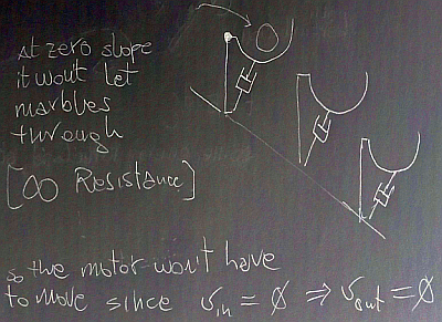

dissipative mechanism - https://i.postimg.cc/K8Rqyrrt/screenshot-6.png

The resistor chain mechanism is weightless and kind of magically glued to the elastic sheet and therefore can be raised by the membrane (whose deformation does not have to take into account the weight of the resistor or the balls inside it).

Transient and perturbations in space
What happens during the initial transient? Well, the throwing of the switch is here represented by the tilting of the generator structure. The rigid structure bring the elastic sheet with it and the conduits immediately adjacent will raise locking into horizontal position - the other end will sink down bringing the rail/conduit down with it. A ball will flow into the lower slot of the generator and the motor will start raising the ball in the lower nearby horizontal rail slot. For every ball taken away from the lower side, a ball is put into the higher side of the generator.
As the balls move along the forming 'raised-lowered' rails, new parts of the conduits lock into horizontal place and the deformation of the sheet proceeds (at high but finite speed) ALONG the longitudinal structure of the circuit.

At the same time, though, the elastic sheet raised at the generator side changes the configuration of the sheet in all space around it, including in the transverse direction ACROSS the circuit. This perturbation of the sheet proceeds at a high but finite speed and when it reaches the resistor (much much earlier than the perturbation of the rails started by the generator arrives there) it will raise and lower its floppy body.

This deformation of the resistor (after a time d/c) will make the balls there fall into the dissipative mechanism, and a current will flow into the resistor well before the rail deformation has gone along the full path of the circuit. It will be a much lower current than that attainable at steady state, but a current nonetheless is flowing.
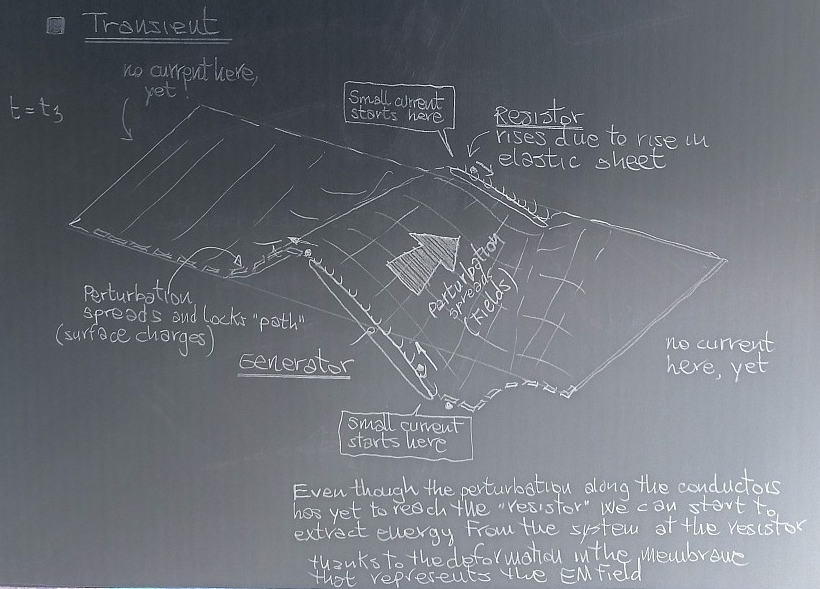

transient with two perturbations - https://i.postimg.cc/HsPz38Dn/screenshot-3.png

Also, the equivalent of KCL is dead here. We can have a current in the lower leg and a different current in the upper leg with no current at all in the rest of the circuit. And no, the balls are not one attached to one other, there is space for local accumulation and rarefaction. Only at steady state we can get a uniform distribution along the circuit and the analogous of KCL obeyed.

Not a friggin' transmission line
What is the purpose (in my deranged mind) for this magi-mechanical model? Illustrate the fact that we have two perturbations that proceed along different directions and that the transmission line model does not consider that 'complication'.
As a matter of fact a transmission line can be 'magi-modeled' by placing the generator on the short leg, and the resistor far away on the opposing short leg.
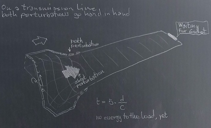

magi-mechanical model of a transmission line - https://i.postimg.cc/jjYzkz8x/screenshot-4.png

In this case both perturbations proceed hand in hand (this is to mimic the use of lumped component for the transverse phenomena) and a transmission line can model the long circuit.

But the magi-mechanical model for the wide circuit shows that in this case one kind of perturbation reaches the load well before the other. The alteration in the fied (here represented by the magical elastic sheet) is accompanied by a local spreading of the second type of perturbation near the resistor, but this is at a level that is well below that attainable at steady state.
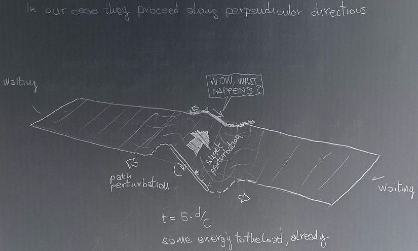

magi-mechanical model of NOT a standard transmission line - https://i.postimg.cc/v8CLVFWx/screenshot-5.png


Is energy actually traveling?
A further consideration can be made about the transport of energy. Is energy traveling at all? In my eyes the energy put into the generator is used to change and keep a configuration of the elastic sheet (and borderline conduits) that makes it possible to extract energy in situ at the resistor.
What propagates for sure is the change in the field in all space around the generator. Then we can extract it wherever the new configuration of field allows us to.

(Now, the process of extracting energy can on its own alter the field, and this perturbation will propagate to the generator that might have to put more energy in in order to maintain the status quo).

All instruments lie. Usually on the bench.
 
The following users thanked this post: hamster_nz

Offline TimFox

  • Super Contributor
  • ***
  • Posts: 8663
  • Country: us
  • Retired, now restoring antique test equipment
Re: "Veritasium" (YT) - "The Big Misconception About Electricity" ?
« Reply #1963 on: May 11, 2022, 10:03:31 pm »
In high-school physics class, ca. 1965, we had a mechanical demonstrator for one-dimensional transmission lines that used a dense set of transverse rods connected to a central torsion spring.
One could propagate a pulse down the rods and see reflections.  Termination options included nothing (open circuit), fixed position (short circuit), and terminated (dashpot for viscous damping).
The propagation speed down the rods was appropriate for human eyesight to see the results.
If I remember correctly, there were different models (different characteristic impedance) to see what happens at discontinuities.
I think this old Mister Wizard demonstration uses the same unit.
 
The following users thanked this post: HuronKing

Offline hamster_nz

  • Super Contributor
  • ***
  • Posts: 2812
  • Country: nz
Re: "Veritasium" (YT) - "The Big Misconception About Electricity" ?
« Reply #1964 on: May 11, 2022, 10:06:06 pm »
I resisted posting this since I didn't want to give wrong ideas to the 'original thinkers' in these threads, but since there already is some sort of discussion on how to mimic the behavior of the circuit with a mechanical model and the apparent necessity for an ether (in the mechanical representation) has already been thrown around, I figured... what the heck.
...

Wow! an epic amount of time and thinking went into that post!
Gaze not into the abyss, lest you become recognized as an abyss domain expert, and they expect you keep gazing into the damn thing.
 

Offline Sredni

  • Frequent Contributor
  • **
  • Posts: 746
  • Country: aq
Re: "Veritasium" (YT) - "The Big Misconception About Electricity" ?
« Reply #1965 on: May 11, 2022, 10:31:03 pm »
If I remember correctly, there were different models (different characteristic impedance) to see what happens at discontinuities.
I think this old Mister Wizard demonstration uses the same unit.


That is John Shive with the... Shive machine.
Yes, it is the best way to learn about impedance matching and reflections.
Shive also wrote a wonderful book:

John N. Shive, Robert Weber
Similarites in Physics
1982, Wiley
273 pp.

Quote from: wikipedia
He made notable contributions in electronic engineering and solid-state physics during the early days of transistor development at Bell Laboratories. In particular, he produced experimental evidence that holes could diffuse through bulk germanium, and not just along the surface as previously thought. This paved the way from Bardeen and Brattain's point contact transistor to Shockley's more-robust junction transistor. Shive is best known for inventing the phototransistor in 1948 (a device that combines the sensitivity to light of a photodiode and the current gain of a transistor), and for the Shive wave machine in 1959 (an educational apparatus used to illustrate wave motion).


All instruments lie. Usually on the bench.
 

Offline aetherist

  • Frequent Contributor
  • **
  • !
  • Posts: 621
  • Country: au
  • The aether will return. It never left.
Re: "Veritasium" (YT) - "The Big Misconception About Electricity" ?
« Reply #1966 on: May 11, 2022, 10:37:06 pm »
I resisted posting this since I didn't want to give wrong ideas to the 'original thinkers' in these threads, but since there already is some sort of discussion on how to mimic the behavior of the circuit with a mechanical model and the apparent necessity for an ether (in the mechanical representation) has already been thrown around, I figured... what the heck.
It reminds me of prep school & grade-1, where we used slate boards & slate pencils & wet sponge to wipe the slate clean.
Then in grade 3 we upgraded to inkwells. I never did do grade-2 – i jumped over it.
But i don’t see any need for an aether here in this gedanken nor in Veritasium's X.
 

Offline HuronKing

  • Regular Contributor
  • *
  • Posts: 247
  • Country: us
Re: "Veritasium" (YT) - "The Big Misconception About Electricity" ?
« Reply #1967 on: May 11, 2022, 11:48:18 pm »
Hot damn that Dr. Shive video is amazing! I'm going to steal that for my classes.
 

Offline aetherist

  • Frequent Contributor
  • **
  • !
  • Posts: 621
  • Country: au
  • The aether will return. It never left.
Re: "Veritasium" (YT) - "The Big Misconception About Electricity" ?
« Reply #1968 on: May 11, 2022, 11:51:00 pm »
In high-school physics class, ca. 1965, we had a mechanical demonstrator for one-dimensional transmission lines that used a dense set of transverse rods connected to a central torsion spring.
One could propagate a pulse down the rods and see reflections.  Termination options included nothing (open circuit), fixed position (short circuit), and terminated (dashpot for viscous damping).
The propagation speed down the rods was appropriate for human eyesight to see the results.
If I remember correctly, there were different models (different characteristic impedance) to see what happens at discontinuities.
I think this old Mister Wizard demonstration uses the same unit.
What a wonderful youtube. I wonder how it applies to elekticity. How duz elekticity reflect off a deadend, or off a change in impedance.
Old (electron) electricity would have it that the drifting electrons are inside the wire. But i reckon that internal electrons contribute very little to electricity.
But my new (elekton) elekticity says that elektons play the major role in some cases.
What do elektons (photons) do when they get to a deadend?  They go straight ahead, koz that is what photons do.
The photons don’t reflect at the deadend, they do a u-turn & hence come back, no reflexion needed.
When i say that elektons do a u-turn i mean that the surface duz a u-turn, the photons don’t know, they are in the dark.

The mechanical analogy for impedance affecting the speed of a mechanical wave has no application in new (elekton) elekticity.
An elekton will propagate along the surface of the wire at a slightly slower than  c/1, due to the slowing/drag of the nearness of mass (& charge attraction).
This drag is of course moreso on the Cu side, hence the photon hugs the Cu.
However, the drag is a very local thing, it is only very slightly affected by Cu that is not local.
Hence the usual equations for impedance of a wire or a pair of parallel wires duz not affect the speed of elekticity, at least not the speed of elektonic elekticity.

When someone duz an X for the speed of elekticity along a bare wire & an insulated wire & a threaded rod, they can place lots of additional rods & wires close up & parallel to the wire being tested, & they will find that the speed of elekticity is not affected by additional wires etc, ie by additional impedance.
« Last Edit: May 20, 2023, 12:56:39 am by aetherist »
 

Offline TimFox

  • Super Contributor
  • ***
  • Posts: 8663
  • Country: us
  • Retired, now restoring antique test equipment
Re: "Veritasium" (YT) - "The Big Misconception About Electricity" ?
« Reply #1969 on: May 12, 2022, 02:56:13 am »
I have seen photons reflect from surfaces (dead ends) when doing photography.
 

Online IanB

  • Super Contributor
  • ***
  • Posts: 12427
  • Country: us
Re: "Veritasium" (YT) - "The Big Misconception About Electricity" ?
« Reply #1970 on: May 12, 2022, 03:18:01 am »
I have seen photons reflect from surfaces (dead ends) when doing photography.

I was struck by the observation that the coating on a camera lens is in fact a quarter-wave impedance matching transformer (it prevents unwanted reflections off the lens surfaces).
 
The following users thanked this post: SilverSolder, HuronKing

Offline aetherist

  • Frequent Contributor
  • **
  • !
  • Posts: 621
  • Country: au
  • The aether will return. It never left.
Re: "Veritasium" (YT) - "The Big Misconception About Electricity" ?
« Reply #1971 on: May 12, 2022, 07:09:59 am »
I have seen photons reflect from surfaces (dead ends) when doing photography.
Yes free photons can indeed reflect from a deadend, ie a photon inside a glass prism can reflect off the end of the glass, ie some do reflect while some don’t (in which case they exit the prism).
Internal reflexion has i think a different cause to external reflexion.
However, i have trouble re how some light can be reflected internally when the incidence is exactly perpendicular (i think this angle is called 00 deg).
External reflexion for 00 deg is i think explainable, but internal reflexion is a worry (for my theory).
The standard explanation for IR involves i think absorption of the photon, & re-emission.  I am sceptical that absorption is the answer.
Anyhow a free photon (an eagle) is a slightly different bird to an elekton (an emu).
Free photon reflexion is i think different to elekton reflexion.  In fact i don’t think that elektons can reflect at all.

I should not call a photon in glass a free photon, but i call it a free photon koz free photons propagate in a straight line, & a photon in glass propagates in a straight line, even tho it is constrained rather than free, ie it is slowed due to drag from the presence of mass (glass), but that drag is evenly distributed all round. I should have called it a gannet or duck rather than an eagle. The photon is sometimes a flying duck (ie a free photon) or a swimming duck (elekton) or a diving duck (no name), or a duck that has bitten its own tail (free electron), or a duck that is orbiting a nucleus (orbiting elektron).

The 6th kind of photon is the neutrino, this is 2 photons that have merged by virtue of sharing their axis (ie photons have a helical main body, with an axis), the 2 photons sitting a half cycle apart, in which case their em fields cancel in the nearfield, in which case a neutrino is very slippery (compared to an ordinary single photon which has a non-zero em field in the nearfield).

https://en.wikipedia.org/wiki/Total_internal_reflection
U might notice that in relation to reflexion wiki mentions an evanescent wave going parallel to the surface of glass.
My elekton is an evanescent photon going parallel to a wire.
« Last Edit: April 29, 2023, 05:36:28 am by aetherist »
 

Offline Berni

  • Super Contributor
  • ***
  • Posts: 5031
  • Country: si
Re: "Veritasium" (YT) - "The Big Misconception About Electricity" ?
« Reply #1972 on: May 12, 2022, 07:58:40 am »
Signal reflection is not electrons bouncing back from the end of a wire like a ball bounces off a wall.

It is more like how waves on the surface of water bounce back from a wall. The magnetic field around the wire keeps pushing electrons along, but once they hit a dead end on the wire they bunch up closer together (this effect is very tiny since packing them only slightly closer massively increases the number of electrons and quickly builds up the required voltage to resist it). At some point they bunch up enough to create enough backwards pressure due to the voltage build up that the magnetic field is reduced down to 0. Yet at this point the electrons are still bunched up creating voltage, so they shove electrons back out of that dead end, creating current and a accompanying magnetic field that then drives the reflected wave back from where it came from.

The voltage and current (or electric and magnetic field) can be thought much like surface height and horizontal velocity in water waves. One affects the other causing them to travel around and interact in all the usual ways. The wave is what travels, not the particles themselves.

The one big difference between water flowing trough pipes and electrons flowing trough wires is that they get there "momentum" mostly from the magnetic field rather than the mass of the particle itself. The electrons move very little in wires and they have very little mass. However this magnetic field is not local to just that one electron, same for the electric field created around the electron. So as a result they can affect other electrons over a significant distance. This is what makes transmission lines act the way they do, also what makes it different than water flowing trough pipes.
 

Offline SilverSolder

  • Super Contributor
  • ***
  • Posts: 6126
  • Country: 00
Re: "Veritasium" (YT) - "The Big Misconception About Electricity" ?
« Reply #1973 on: May 12, 2022, 12:29:16 pm »
I have seen photons reflect from surfaces (dead ends) when doing photography.
Yes free photons can indeed reflect from a deadend, ie a photon inside a glass prism can reflect off the end of the glass, ie some do reflect while some don’t (in which case they exit the prism).
Internal reflexion has i think a different cause to external reflexion.
However, i have trouble re how some light can be reflected internally when the incidence is exactly perpendicular (i think this angle is called 00 deg).
External reflexion for 00 deg is i think explainable, but internal reflexion is a worry (for my theory).
The standard explanation for IR involves i think absorption of the photon, & re-emission.  I am sceptical that absorption is the answer.
Anyhow a free photon (an eagle) is a slightly different bird to an electon (an emu).
Free photon reflexion is i think different to electon reflexion.  In fact i don’t think that electons can reflect at all.

I should not call a photon in glass a free photon, but i call it a free photon koz free photons propagate in a straight line, & a photon in glass propagates in a straight line, even tho it is constrained rather than free, ie it is slowed due to drag from the presence of mass (glass), but that drag is evenly distributed all round. I should have called it a gannet or duck rather than an eagle. The photon is sometimes a flying duck (ie a free photon) or a swimming duck (electon) or a diving duck (no name), or a duck that has bitten its own tail (free electron), or a duck that is orbiting a nucleus (orbiting electron).

The 6th kind of photon is the neutrino, this is 2 photons that have merged by virtue of sharing their axis (ie photons have a helical main body, with an axis), the 2 photons sitting a half cycle apart, in which case their em fields cancel in the nearfield, in which case a neutrino is very slippery (compared to an ordinary single photon which has a non-zero em field in the nearfield).

https://en.wikipedia.org/wiki/Total_internal_reflection
U might notice that in relation to reflexion wiki mentions an evanescent wave going parallel to the surface of glass.
My electon is an evanescent photon going parallel to a wire.

There is always going to be some diffusion, however miniscule it may be...   - in the real world, we don't have perfect reflectors?
 

Offline penfold

  • Frequent Contributor
  • **
  • Posts: 675
  • Country: gb
Re: "Veritasium" (YT) - "The Big Misconception About Electricity" ?
« Reply #1974 on: May 12, 2022, 02:12:33 pm »
..
Anyway, interesting point you (adx) made previously about the hydraulic analogy... I did wonder, much earlier on, whether Derek was simply setting us up for a video entitled "The big misconception about hydraulics". Extending the "rubber hoses in air" (the hoses being somewhat compliant and able to transmit a pressure wave), I wondered what would happen if the hydraulic circuit were constructed, rather than with tube in air, with cavities, channels, or tunnels within a soft and gelatinous medium (low-durometer silicone rubber perhaps). [...]

That's certainly an interesting thought. I was trying to work out how a fluid analogy of a transformer would work some time back, and worked something out based on sort of similar principles - but hadn't thought of making a hydraulic circuit with "radiation". My mind boggles at the opportunities (none of them business!). Little embedded air bubbles to visualise it? Would mercury be too heavy? Advertising opportunities on YouTube maybe (as SiliconeAether?), high speed cameras, sounds like a fun thing to do.

Yeah... the fluid transformer analogy has me stumped a little bit, at least I just can't imagine it quite. A capacitor could easily work like a bladder pump (used in groundwater and deep bore-hole sampling) and I'm imagining some transmission line coupling similar to a peristaltic pump due to a wave of pressure fluctuations, giving some transmission line characteristics. With a jelly-like medium, I like the way it separates the E-field-like and H-field-like components (we can have a permanent displacement, but no continuous velocity)... but can't quite think of a good H-field equivalent, possibly on a geological timeframe with lava flows or shorter times in weather systems... time to revise some fluid dynamics.

Mercury could be a good fluid to use... in small quantities, I'm sure it wouldn't sink through gelatine, and being conductive it would be easy to measure spikes in pressure from it jumping up in risers/vents at strategic points. But... yeah... it's utterly useless I guess, maybe it's a good analogy of a non-real view of electricity without DC magnetism, otherwise, just food for thought (though... maybe hold the mercury in the jelly).


Share me

Digg  Facebook  SlashDot  Delicious  Technorati  Twitter  Google  Yahoo
Smf