Enough nonsense—back to the original question.
I have two similar-size cylinders with axial leads.
One is an RN65D metal-film resistor.
Testing it, I see that it obeys Ohm’s law quite well, but has small parasitic inductance and capacitance, along with a slight self-heating and temperature co-efficient.
Ignoring the minor deviations from the Platonic ideal, I confirm the common opinion that it be called “resistor”.
The other is labeled 1N4007.
Initial measurements show it is not close to Ohmic, especially with respect to polarity reversal.
Testing it, I see that it conforms well to Shockley’s equation for a semiconductor diode (including temperature effects) with small parasitic series resistance (in the package), along with non-linear junction capacitance and charge storage.
Again, following your advice to ignore secondary effects, I confirm its proper name as “diode”.
Calling it a “resistor” would only be confusing.
Ok, this is the VI characteristic of a 1N4148 diode in LTSpice (default temperature) - sorry I went on simulating and picked 1n4148 instead of 1n4007. But it's immaterial.

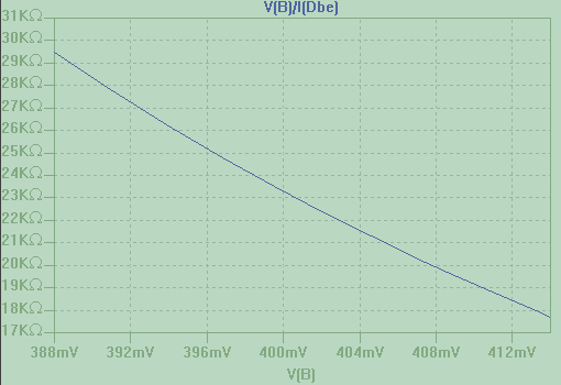
and this is the resistance offered by the diode as a function of the voltage across it

So, we are now seeing the diode as a voltage dependent resistor. Let's see... what is the resistance 400mV? Let's zoom in:

I'd say it's about 23.2 kohm.
Let's see what is the resistance at, I don't know, 660 mV (about 5mA of diode current). We can compute it by hand of course, but on the graph we see it is 132 ohm.

Now, let's see if we can make something with these values...
Let's say I have a 5V supply and a diode that has exactly that characteristic (you can find yours experimentally at your lab temp).
If the diode at 5mA shows a resistance of 132 ohms, we can create a circuit that drives 5mA by using a resistor such as
5mA (Rx + Rdiode) = 5V
or Rx = 5V / 5mA - 132 = 1000 - 132 = 868 ohm
Oh, look: 660 mV voltage, 5 mA current. What a lucky break.

How about the other one?
The diode shows 23.2 kohm at 0.4V.
Let's change equation, since I did not record the current. Let's use a voltage divider equation
Rdiode/ (Rx + Rdiode) 5V = 0.4V
23.2k / (Rx + 23.2k) = 0.4 / 5
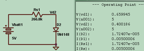
Rx = 23.2k 5 / 0.4 - 23.2k = 266.8 kohm
and, oh look:

0.4V.
Now, let's see what we can do with resistors:

Ok, exact same results, if we neglect a bit of rounding error in reading and setting the values.
Now, take your black boxes out of the fridge. Put the diodes D1 and D2, and the resistors R1 and R2 inside a black box each. Shuffle them around. And tell me: without looking inside the black boxes and without resorting to second order effects (like temperature dependence, or changing the other circuital parameters to change the operating points) can you tell me which are the diodes and which are the resistors, by simply measuring voltages, currents and powers?