Hi Dave, Merry Christmas.
I used to work for IBM in the late seventies and early eighties doing electronic repair on all types of IBM systems.
The unit that you have was indeed used for mainframe diagnostics back in the day. And yes, we had a number of these suitcases in New Zealand so there would have been a lot of them made.
I never worked on mainframes so I never used one of these but I did repair a couple.
Field Engineers would often shut the case, with the diskette still inserted, and bend it over. Not a great design!
The diskette had all the code (Microcode in IBM speak) to boot up the device and get it functional. From distant memory, the display should show an error if the diskette was not inserted on power on.
Thats about all I can remember about the unit but I do know a few things about the grid PCBs.
I don't know what IBM called the style of that grid arrangement but it was used in the majority of IBM equipment in the 70s and 80's. (Terminals, modems, mainframes, mid range systems, communication controllers, disk drives, tape drives, electronic typewriters, matrix and line printers. Pretty much everything.)
It is multilayer, four layer at least, with plated through pads at 0.1" everywhere. I think that IBM must have had a process to make them that could easily have the traces added where needed. So you could place chips and passive components anywhere on the board and use all the other holes as vias.
Most boards have spring contacts soldered along the edges and green plastic covers snapped over them. Some boards have these connectors on both ends of the board and once plugged into the main mother board, crossover connectors connected the rears of boards where necessary. The boards also typically had a plastic frame clipped around them that had guides and eject levers so engineers could easily insert and remove them from equipment. (Not so in space constrained test gear.)
Just some other information.
Bypass capacitors, when used, where typically single caps (Not arrays). They where pretty much the same size as the resistor arrays but only 2 pins long.
The big silver aluminium cans.. We called these 'Duchess Modules' (Their code name. Everything in IBM had a code name.) They were always through hole (I know as I have desoldered thousands of them.) They came in different pin configurations depending on the number of wires that the chip needed. There were literally hundreds of different types. The IBM PS/2 (1987) even used them.
The smaller cans had different configurations too. Sometimes they where as simple as just containing four transistors.
And finally for those who want a blast from the past..
IBM created circuit diagrams of their equipment using line flow printers (No graphic laser printers back in the 70s and 80s.) These massive printouts, called Automated Logic Diagrams (ALD) where a site to behold.
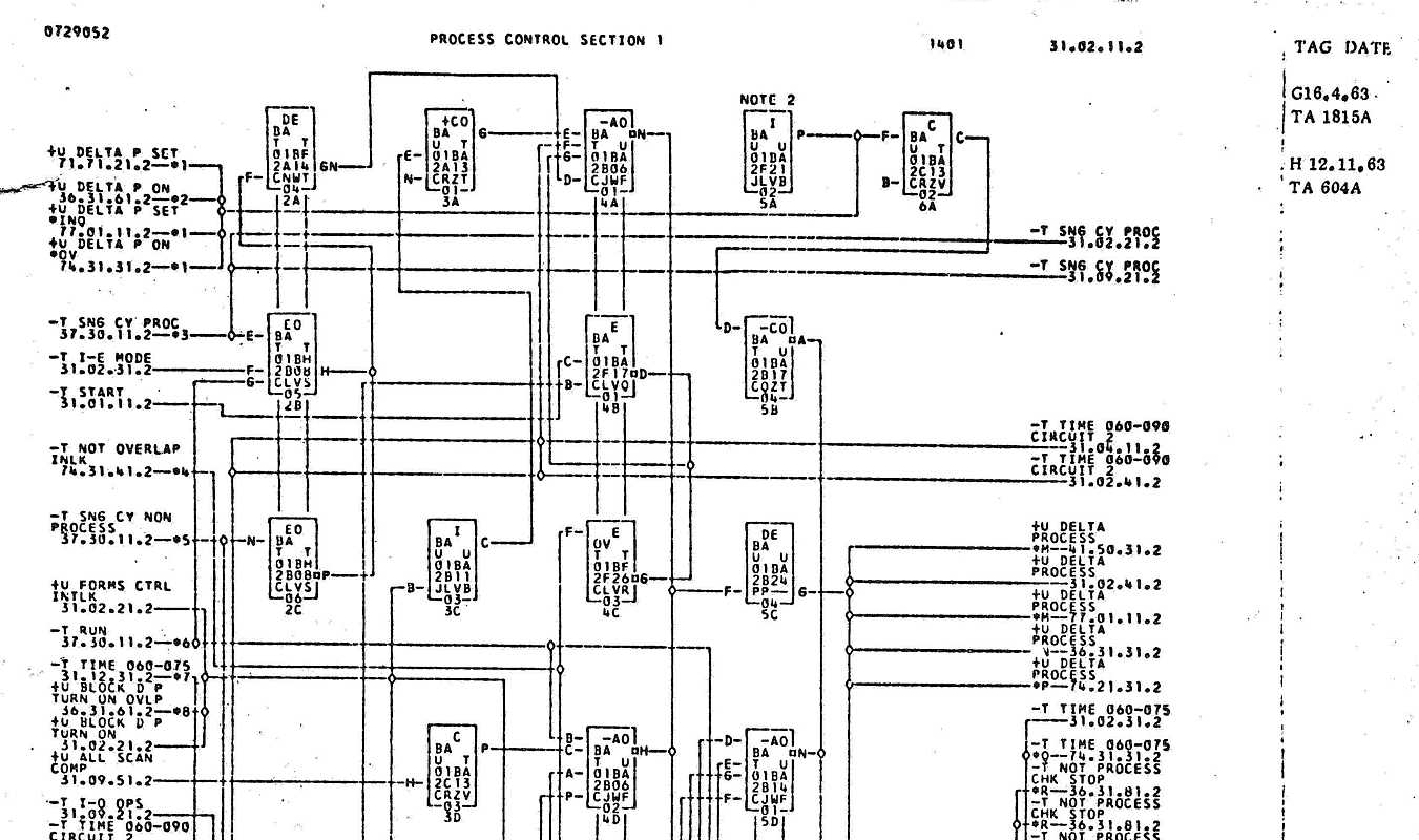
And I do remember a couple of the ALD pages for an IBM 3741 (Like a card punch machine but it wrote to 8" diskettes instead of punching cards) that were labeled C3PO and R2D2. IBM engineers had a sense of humour...

Alien


