Today, I did some experiments with an ADF4360 evaluation board. The board I have (for the ADF4360-9) was from some time ago, so I spent some time firstly checking it worked as is, then converting it to an ADF4360-7 board.
In short, with the parts believed to make up the DS1000Z loop filter, and with the new firmware, the eval board locks solidly. With the old firmware, it does _not_ lock.
Unfortunately this probably brings up more questions than it answers, in that the loop filter parts on the eval board seem to work.
New firmware on Eval board with DS1000Z loop filter parts
Old firmware on Eval board with DS1000Z loop filter parts
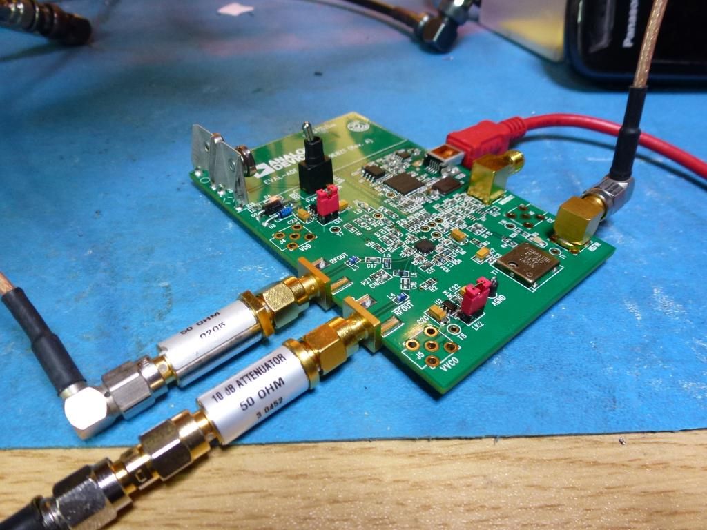
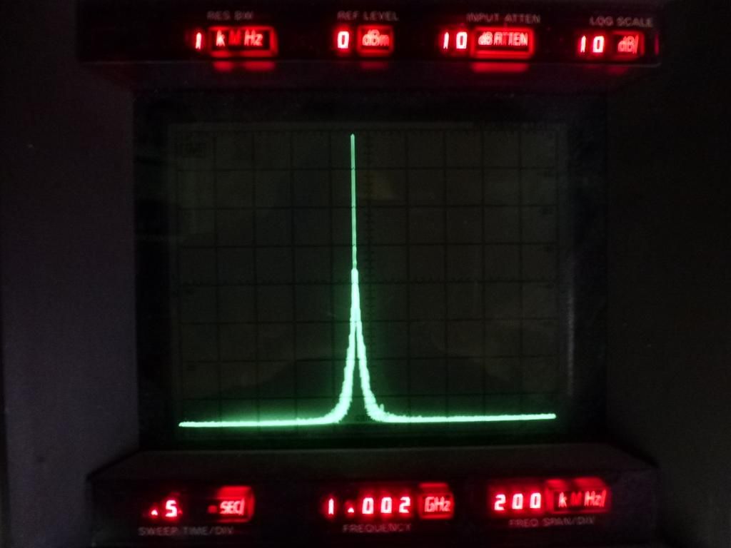
Eval board setup
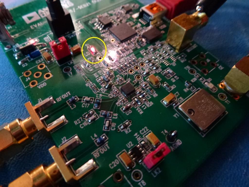
Eval board "lock" LED
Detail of testsThe ADF4360-9 eval board was populated with parts as per the ADF4360-7 eval board BOM/schematics. It was tested at the default 900MHz offered by the ADF4360 software package, and all seemed to work reasonably well. When trying to use the board above about 983MHz, the device unlocked. I adjusted the inductors L1 and L2 as per the datasheet calculation "Choosing the Correct Inductance Value" to 3.3nH (were 3.9nH). The board then worked fine at 1GHz with the software's default settings. Please see attached PDF for the mods made to the eval board, in a semi DaveCAD style.
The software settings were then adjusted to match the newly released firmware register settings.
o Test 1: Default eval board parts, new firmware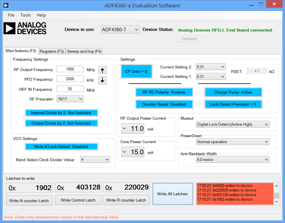
New firmware ADF4360-7 register settings
Eval board with default parts (except L1 and L2, see text) and new firmware register settings (10MHz span)
The board's LED was showing "locked" and on a scope the MUXOUT pin was steady high indicating the device is locked according to the digital lock. As the results were promising, the same test was performed with the original firmware register settings.
o Test 2: Default eval board parts, old firmware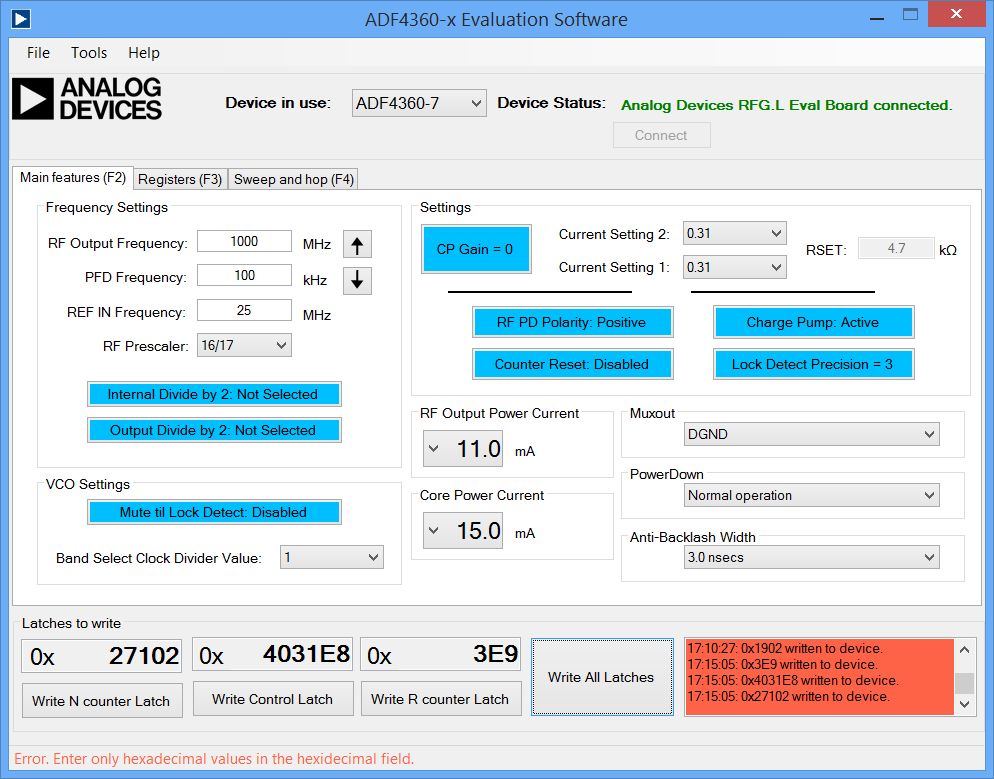
Old firmware ADF4360-7 register settings
Eval board with default parts (except L1 and L2, see text) and old firmware regsiter settings (10MHz span)
Eval board with default parts (except L1 and L2, see text) and old firmware regsiter settings (2MHz span)
On this occasion, the lock LED was off indicating there was no lock.
The next tests are duplicating those above but with the default eval board loop filter parts replaced with those believed to be on the DS1000Z.
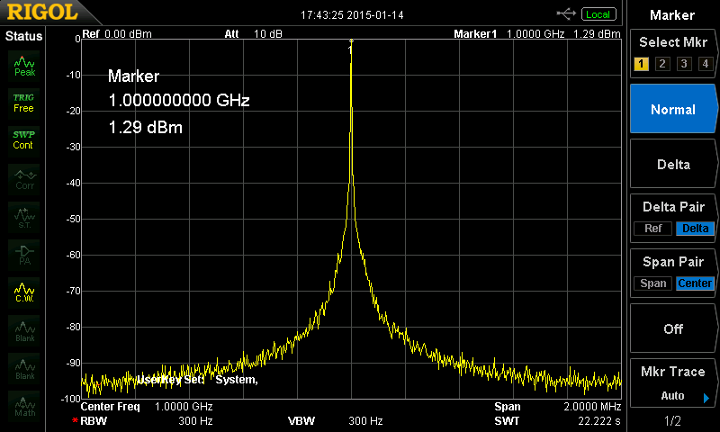
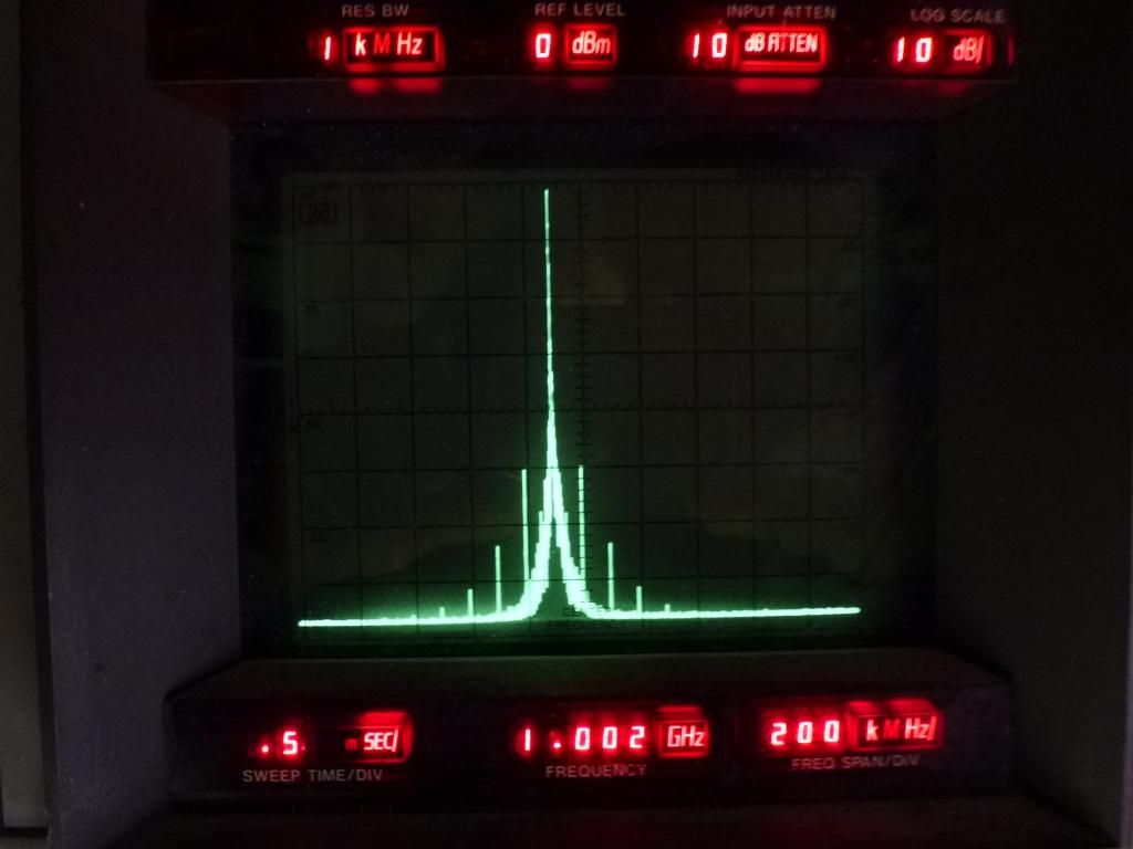
o Test 3: DS1000Z loop filter parts on eval board, new firmware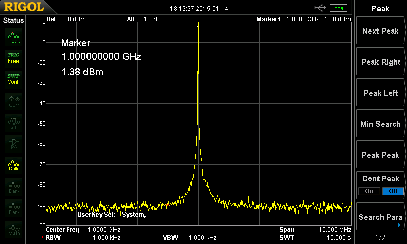
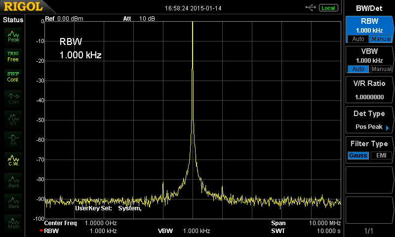
Eval board with DS1000Z loop filter parts, and L1 & L2 set as in text, new firmware settings (10MHz span)
Eval board with DS1000Z loop filter parts, and L1 & L2 set as in text, new firmware settings (2MHz span)
This one's for Bud ;-)
With the new firmware and the DS1000Z loop filter parts (and keeping L1+L2 3.3nH) the lock LED came on, and was showing solid on the scope.
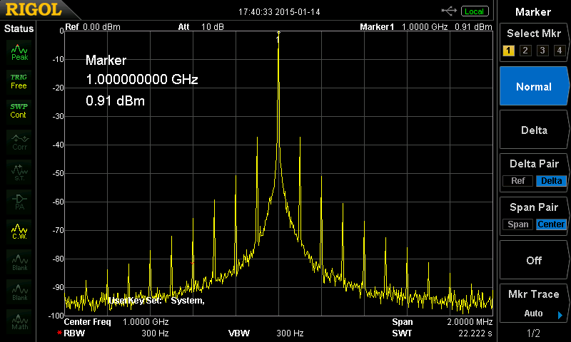
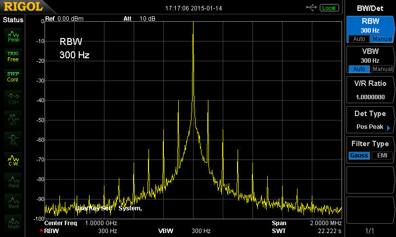
o Test 4: DS1000Z loop filter parts on eval board, old firmware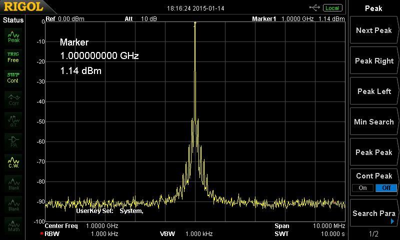
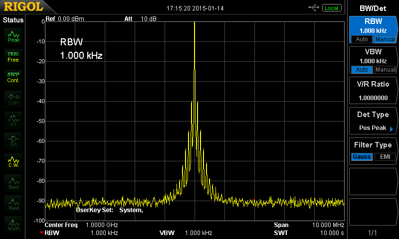
Eval board with DS1000Z loop filter parts, and L1 & L2 set as in text, old firmware settings (10MHz span)
Eval board with DS1000Z loop filter parts, and L1 & L2 set as in text, old firmware settings (2MHz span)
Specially made Bud version ;-)
Part modifications from the default ADF4360-7 eval board schematic/BOMo L1 & L2 reduced from 3.9nH to 3.3nH as per data sheet for VCO operation at 1GHz.
o Loop filter (Eval board default / DS1000Z)
- R10 8.2k / 909R
- R11 4.3k / 3.65k
- C13 560p / 5.5n
- C14 8.2n / 24n
- C15 270p / 750p
ConclusionThe loop filter parts, as they are understood to be, lock on the eval board. Why they would not lock on the scope itself remains a mystery. It is interesting to note that the old firmware does not present LOCK on the MuXOUT pin. The new firmware does however. The spurs are marginally worse with the DS1000Z filter loop parts. I should note that if L1 and L2 are not right, indications are that the VCO simply goes off into la la land, it's not just a little bit of FMing. Perhaps it's a layout, power or decoupling issue that's modulating the carrier. Sorry I couldn't give a more concrete result, however if those of you brave enough would like to check pin 20 on the ADF4360-7 on their scope, if it is locked it'll be sitting pretty at 3.3V. Note that that won't tell you anything on the old firmware as the lock signal didn't come out on the MUXOUT pin.


