Author Topic: EEVblog #1104 - Omicron Labs Bode 100 Teardown  (Read 113751 times)

0 Members and 2 Guests are viewing this topic.

Offline precaud

  • Frequent Contributor
  • **
  • Posts: 734
  • Country: us
    • LinearZ
Re: EEVblog #1104 - Omicron Labs Bode 100 Teardown
« Reply #75 on: July 25, 2018, 02:21:07 pm »
All this good transformer work really should be moved to its own thread in an appropriate forum...
 

Offline capt bullshot

  • Super Contributor
  • ***
  • Posts: 3033
  • Country: de
    • Mostly useless stuff, but nice to have: wunderkis.de
Re: EEVblog #1104 - Omicron Labs Bode 100 Teardown
« Reply #76 on: July 25, 2018, 06:55:50 pm »
Made another two transformers using that salvaged VAC core. Used bifilar (non-twisted) winding, PTFE isolated.

Results

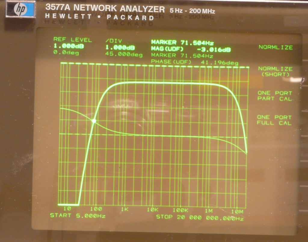
1st one made with one layer of turns, resulting in about 30 turns, the core has 62µH/n²
-3dB response is from 71Hz to 14MHz, one can see about 0.2dB transmission loss.
The former one that was wound using twisted pair from ethernet cable has near zero losses, so I believe these losses are due to the wire's resistance.


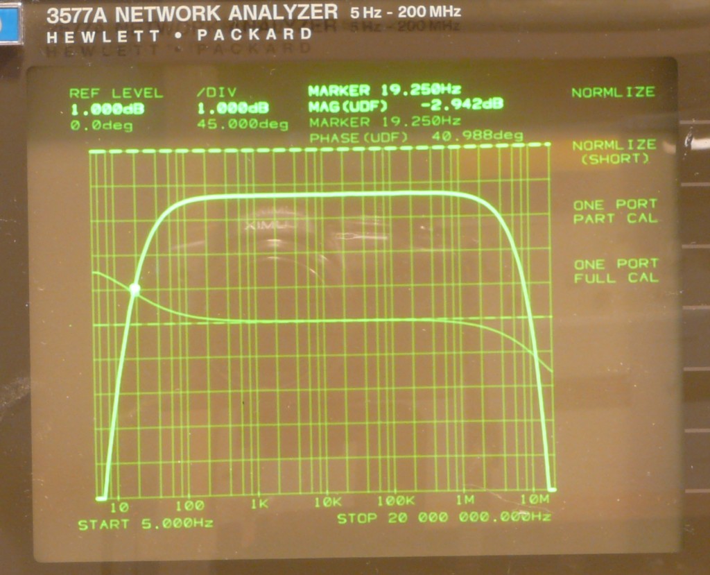
2nd one made with two layers of turns, about four times the magnetizing inductance, resulting in
-3dB response from 19Hz to 8.4MHz, somewhat more loss, maybe 0.3dB. It's not exactly a fourth of the 1st ones LF response, this is because I cut the wire somewhat too short, wasn't enough for 60 turns.



And now for something completely different:
I've connected them to the TDR to measure the wire length and see the transmission line's impedance:
Todays 1st one:


Todays 2nd:


And for comparison, this one from last week to point out the difference between bifilar and twisted pair winding:


One can clearly see, the impedance over wire length is flatter for the twisted pair, but it appears to have none or very little effect on the frequency response.
« Last Edit: July 25, 2018, 07:05:42 pm by capt bullshot »
Safety devices hinder evolution
 
The following users thanked this post: thm_w, ogden, The Soulman

Offline rx8pilot

  • Super Contributor
  • ***
  • Posts: 3644
  • Country: us
  • If you want more money, be more valuable.
Re: EEVblog #1104 - Omicron Labs Bode 100 Teardown
« Reply #77 on: July 28, 2018, 01:12:58 am »
Made another two transformers using that salvaged VAC core. Used bifilar (non-twisted) winding, PTFE isolated.

Results

I just got my 3577A repaired.....just trying to figure how it works now. So far, I have not actually used it.......

I have some transformers and parts to take a shot at this but need to make sure I am setting up the test correctly.
« Last Edit: July 28, 2018, 02:50:12 am by rx8pilot »
Factory400 - the worlds smallest factory. https://www.youtube.com/c/Factory400
 

Offline capt bullshot

  • Super Contributor
  • ***
  • Posts: 3033
  • Country: de
    • Mostly useless stuff, but nice to have: wunderkis.de
Re: EEVblog #1104 - Omicron Labs Bode 100 Teardown
« Reply #78 on: July 28, 2018, 07:19:17 am »
I've made these measurements with the transformer terminated by the 50Ohm input. Switching the input to high impedance and using an 10Ohm resistor to terminate the transformer gives different results. The low -3dB is shifted down to below 10Hz with the second transformer, the upper end -3dB gets about 7MHz.

Don't forget to normalize the 3577A (with no transformer, but termination as wanted). I've used log sweep from 5Hz to 20Mhz , 120s (or 60s) sweep time and 1Hz RBW, auto RBW off.

I've made this simple test rig, the switches are used to bypass the DUT, one can see the 10Ohm termination resistor placed into the pin sockets. The upper left SMB connector isn't used for anything, just in case you wonder.
« Last Edit: July 28, 2018, 07:34:38 am by capt bullshot »
Safety devices hinder evolution
 

Offline DualTriode

  • Contributor
  • Posts: 18
  • Country: us
Re: EEVblog #1104 - Omicron Labs Bode 100 Teardown
« Reply #79 on: July 30, 2018, 02:17:31 am »
Hello, 

My first post here.

California is on fire, when the smoke clears I will test this thing.

The VAC T60006-L2030-W514-03- core appears to be an exact match for size and color for the core in the real B-Wit injection transformer.

https://www.mouser.com/datasheet/2/599/W514-238036.pdf

See the attached photo of the real deal side by side with a home rolled version. The home rolled version has 40 turns of twisted pair CAT 6 plenum wire.

Thanks DT
 
The following users thanked this post: voltsandjolts

Online Hydron

  • Super Contributor
  • ***
  • Posts: 1043
  • Country: gb
Re: EEVblog #1104 - Omicron Labs Bode 100 Teardown
« Reply #80 on: July 30, 2018, 09:11:34 am »
Nice, looks like the closest match yet (physically at least)!

Seems that Dave's "Nude Austrian virgins" line suckered a bunch of us into proving him wrong :P To be fair it is a relatively exotic core material.
 

Offline precaud

  • Frequent Contributor
  • **
  • Posts: 734
  • Country: us
    • LinearZ
Re: EEVblog #1104 - Omicron Labs Bode 100 Teardown
« Reply #81 on: August 01, 2018, 04:56:11 pm »
I thought it might be useful context to show what 50-Ohm isolation xfrms are available on the used market for relatively little money.

Here are the plots of two North Hills 50-Ohm Isolation Transformers, models 0016 PA and 0017 CC. They have been around for more than 20 years, and the latter has been on HP/Agilent's recommended list for about that long. I don't know why HP never mentioned the 0016, because its the better. These measurements are made with 50 Ohm source and termination, into 1M inputs. The Anritsu VNA only goes down to 10Hz so a separate measurement was made down to 1Hz.

As you can see, both units have very good LF extension, less than -3dB down @ 1 Hz. Reducing the source impedance extends it further. On the high end, the 0016 is -3dB at about 24MHz and the 0017 to 7.5MHz. Response shape above a few MHz is greatly impacted by analyzer input and cable reactances. Best plan is to terminate the xfmr right at the secondary output.

These things generally go for 30-60 bucks when they show up on eBay.
 

Offline DualTriode

  • Contributor
  • Posts: 18
  • Country: us
Re: EEVblog #1104 - Omicron Labs Bode 100 Teardown
« Reply #82 on: August 02, 2018, 03:55:22 am »
Hello,

Went out through the wild fire smoke to the shop.

I tested both the real B-WIT injection transformer and the Home-Roll.

Pretty much Same Same.

Thanks DT
 
The following users thanked this post: precaud

Offline precaud

  • Frequent Contributor
  • **
  • Posts: 734
  • Country: us
    • LinearZ
Re: EEVblog #1104 - Omicron Labs Bode 100 Teardown
« Reply #83 on: August 02, 2018, 04:04:39 am »
Thanks for posting this. Not much different from the NH 0016 tested above.
 

Offline ace1903

  • Regular Contributor
  • *
  • Posts: 240
  • Country: mk
Re: EEVblog #1104 - Omicron Labs Bode 100 Teardown
« Reply #84 on: August 02, 2018, 09:15:18 am »
There is cheap source of vitroperm cores in RCD switches. I took one from hardware store for ~10eur.
Obviously it is smaller when compared with "original"  one. Don't know if 300mA has bigger core.
Anyone interested to make measurement and compare results?
I have LCR meter but don't have network analyser.   
Attached picture of RCD Commel 470-025 with core opened from protective plastic.
 

Offline capt bullshot

  • Super Contributor
  • ***
  • Posts: 3033
  • Country: de
    • Mostly useless stuff, but nice to have: wunderkis.de
Re: EEVblog #1104 - Omicron Labs Bode 100 Teardown
« Reply #85 on: August 02, 2018, 09:58:41 am »
You could measure the inductance of one turn.
This value should be larger than 60uH to make the core interesting, I've also had tested some cores with 20uH / n^2, they didn't give satisfactory results (too many turns required for the low frequency rolloff, killing the high frequency response).

Safety devices hinder evolution
 

Offline ace1903

  • Regular Contributor
  • *
  • Posts: 240
  • Country: mk
Re: EEVblog #1104 - Omicron Labs Bode 100 Teardown
« Reply #86 on: August 02, 2018, 10:48:43 am »
Measured with Voltcraft LCR-300 single turn:
88uH at 100Hz Q2.62
87uH at 120Hz Q 2.92
79uH at 1kHz Q4.62
46.6uH at 10kHz Q1.642
8.46uH at 100kHz Q0.668

Is this drop at 100kHz expected? I mostly do embedded programming and digital electronics and I maybe did some error during measurement( with 8 turns results are similar with more drastic drop).
I also own Analog Discovery 1 and probably can do some kind of transfer characteristic measurement but I lack knowable how to make measurement set up.
Where to put resistors and with which value?
 

Offline capt bullshot

  • Super Contributor
  • ***
  • Posts: 3033
  • Country: de
    • Mostly useless stuff, but nice to have: wunderkis.de
Re: EEVblog #1104 - Omicron Labs Bode 100 Teardown
« Reply #87 on: August 02, 2018, 01:31:13 pm »
Yes, that drop in inductance is to be expected for that kind of core.
If you manage to apply 40 ... 50 turns of twisted pair or bifilar as done before here in this thread, I'd expect a pretty low frequency limit for it. Upper limit depends on the length of wire, try not to get longer than 2 ... 3 meter.

So, now take the wires of same colour as input / output of this transformer, you should measure (number of turns)^2 * 79uH @ 1kHz as the magnetizing inductance at either input and output. Short output and measure the inductance of input, you get the stray inductance, that should be pretty low for this construction.

Next apply a function generator at the input, connect a 10 Ohm resistor across the output and measure voltage across that output. Sweep frequency from 1Hz (or whatever is lowest possible) to 20Mhz at a rather low level (< 1Vpp) and draw the frequency response (bode plot). This should get similar results to the posted plots. This measurement includes the loading of the transformer / 10R to the generators output and differs from the transformers response. For an advanced measurement, apply the same generator to the input, keep the 10R termination and measure both voltages (input and output) at the same time, then calculate their ratio - this gives the transformers response alone. I'm not familiar with the Analog Discoveries possibilities, it should offer some kind of Bode Plot feature with two input voltages and one generator output, this is what you want.


Safety devices hinder evolution
 

Offline precaud

  • Frequent Contributor
  • **
  • Posts: 734
  • Country: us
    • LinearZ
Re: EEVblog #1104 - Omicron Labs Bode 100 Teardown
« Reply #88 on: August 02, 2018, 01:53:09 pm »
Next apply a function generator at the input, connect a 10 Ohm resistor across the output and measure voltage across that output. Sweep frequency from 1Hz (or whatever is lowest possible) to 20Mhz at a rather low level (< 1Vpp) and draw the frequency response (bode plot). This should get similar results to the posted plots. This measurement includes the loading of the transformer / 10R to the generators output and differs from the transformers response.

Why the 10R? Does that reflect how you most often use them?
 

Offline capt bullshot

  • Super Contributor
  • ***
  • Posts: 3033
  • Country: de
    • Mostly useless stuff, but nice to have: wunderkis.de
Re: EEVblog #1104 - Omicron Labs Bode 100 Teardown
« Reply #89 on: August 02, 2018, 02:12:59 pm »
Next apply a function generator at the input, connect a 10 Ohm resistor across the output and measure voltage across that output. Sweep frequency from 1Hz (or whatever is lowest possible) to 20Mhz at a rather low level (< 1Vpp) and draw the frequency response (bode plot). This should get similar results to the posted plots. This measurement includes the loading of the transformer / 10R to the generators output and differs from the transformers response.

Why the 10R? Does that reflect how you most often use them?


10R is the value the Omicron transformer is specified for (recommended 1R ,,, 10R afair). Just to be comparable - e.g. I did the measurements for my home rolled transformer with 50R termination and get different results.
Safety devices hinder evolution
 

Offline T3sl4co1l

  • Super Contributor
  • ***
  • Posts: 22436
  • Country: us
  • Expert, Analog Electronics, PCB Layout, EMC
    • Seven Transistor Labs
Re: EEVblog #1104 - Omicron Labs Bode 100 Teardown
« Reply #90 on: August 02, 2018, 02:20:03 pm »
Yes, skin effect dominates by ~20kHz or so, at which point the core resembles a Warburg element.

Example:


Approximate equivalent circuit:


An upside to this for EMC purposes: the Q is very low as the impedance rises towards peak, so that you can pair the CMC with a modest capacitance and not worry about resonance.  Because the mu, going into this region, starts higher than it is for ferrite, and hi-mu ferrite drops off (~single pole) at a roughly similar frequency (usually ~100kHz, but depends on core size), nanocrystalline has a wider and taller impedance peak than ferrite does, making it just that bit better.

Tim
Seven Transistor Labs, LLC
Electronic design, from concept to prototype.
Bringing a project to life?  Send me a message!
 

Offline Bud

  • Super Contributor
  • ***
  • Posts: 7130
  • Country: ca
Re: EEVblog #1104 - Omicron Labs Bode 100 Teardown
« Reply #91 on: August 02, 2018, 02:36:03 pm »
Quote
Why the 10R? Does that reflect how you most often use them?
Quote
10R is the value the Omicron transformer is specified for (recommended 1R ,,, 10R afair). Just to be comparable - e.g. I did the measurements for my home rolled transformer with 50R termination and get different results.

Low value load impedance Because of the way injection transformers are used. To inject the signal into the power supply control loop you break the control loop connection and insert a low value resistor in it in series across which you then connect the injection transformer. Resistor values up to 10 Ohm seem to be reasonable to not have effect or have minimal effect on the control loop under test. 50 Ohm may be too high, i'd shoot for and test with 10 Ohm.
Facebook-free life and Rigol-free shack.
 

Offline precaud

  • Frequent Contributor
  • **
  • Posts: 734
  • Country: us
    • LinearZ
Re: EEVblog #1104 - Omicron Labs Bode 100 Teardown
« Reply #92 on: August 02, 2018, 02:54:25 pm »
Quote
Why the 10R? Does that reflect how you most often use them?
Quote
10R is the value the Omicron transformer is specified for (recommended 1R ,,, 10R afair). Just to be comparable - e.g. I did the measurements for my home rolled transformer with 50R termination and get different results.

Low value load impedance Because of the way injection transformers are used. To inject the signal into the power supply control loop you break the control loop connection and insert a low value resistor in it in series across which you then connect the injection transformer. Resistor values up to 10 Ohm seem to be reasonable to not have effect or have minimal effect on the control loop under test. 50 Ohm may be too high, i'd shoot for and test with 10 Ohm.

OK, got it. I've not done it myself, but most of the R's I've seen used for control loop repose were higher than 10R, more like 33-50.
 

Online Hydron

  • Super Contributor
  • ***
  • Posts: 1043
  • Country: gb
Re: EEVblog #1104 - Omicron Labs Bode 100 Teardown
« Reply #93 on: August 02, 2018, 03:06:47 pm »
50R seems reasonable unless the feedback divider values are unusually low. When I've done this type of testing (using a video isolation transformer, as I did not have my isolated sig-gen available) 50R worked well. The actual value will not be critical as long as it's reasonable.
 

Offline Wolfgang

  • Super Contributor
  • ***
  • Posts: 1820
  • Country: de
  • Its great if it finally works !
    • Electronic Projects for Fun
Re: EEVblog #1104 - Omicron Labs Bode 100 Teardown
« Reply #94 on: August 02, 2018, 03:27:28 pm »
Another reason to use a very low termination resistor for an injection transformer is bandwidth. The lower the termination resistor, the higher the bandwidth.
Another trick to increase bandwidth in an injection transformer is a (lossy) matching network at the primary side. This damps out resonances and flattens frequency response.  :)

Enhanced by these tricks, even very normal off-the-shelf signal transformers can be successfully used up to a few 100kHz.
The loss is normally no problem because the injected signal needs to have a very low amplitude.

https://electronicprojectsforfun.wordpress.com/injection-transformers/

shows some of these.


Offline precaud

  • Frequent Contributor
  • **
  • Posts: 734
  • Country: us
    • LinearZ
Re: EEVblog #1104 - Omicron Labs Bode 100 Teardown
« Reply #95 on: August 02, 2018, 03:33:37 pm »
Another reason to use a very low termination resistor for an injection transformer is bandwidth. The lower the termination resistor, the higher the bandwidth

Hmmm... I see exactly the opposite. I'll post some results later.
 

Offline DualTriode

  • Contributor
  • Posts: 18
  • Country: us
Re: EEVblog #1104 - Omicron Labs Bode 100 Teardown
« Reply #96 on: August 02, 2018, 06:34:49 pm »
Hello,

For grins this is a plot of the Jensen ISO-MAX VB-1BB 75 Ohm isolation transformer on ebay for $20. Not bad for $20, if price is the object.

The second plot is the Home-Roll. Can't tell it from the B-WIT.

Both plots 401 test points from 1Hz to 25MHz

Thanks DT
« Last Edit: August 02, 2018, 06:40:41 pm by DualTriode »
 
The following users thanked this post: thm_w

Offline rx8pilot

  • Super Contributor
  • ***
  • Posts: 3644
  • Country: us
  • If you want more money, be more valuable.
Re: EEVblog #1104 - Omicron Labs Bode 100 Teardown
« Reply #97 on: August 02, 2018, 07:16:57 pm »
I have the same Jensen ISO-MAX.... seems like a great bang for your buck.

Short and misplld from my mobile......

Factory400 - the worlds smallest factory. https://www.youtube.com/c/Factory400
 

Offline precaud

  • Frequent Contributor
  • **
  • Posts: 734
  • Country: us
    • LinearZ
Re: EEVblog #1104 - Omicron Labs Bode 100 Teardown
« Reply #98 on: August 03, 2018, 03:12:42 am »
Another reason to use a very low termination resistor for an injection transformer is bandwidth. The lower the termination resistor, the higher the bandwidth.

Here's the NH 0016PA transformer with 50 Ohm source and 1 terminated with 50, 10, and 1 Ohm. Bandwidth goes from >20MHz @ 50 Ohms to ~150kHz @ 1 Ohm. This is pretty typical of the better 1:1 xfmrs I've looked at. You can get a little of the bandwidth back with lower source R.
 

Offline DualTriode

  • Contributor
  • Posts: 18
  • Country: us
Re: EEVblog #1104 - Omicron Labs Bode 100 Teardown
« Reply #99 on: August 03, 2018, 05:07:58 am »
Hello,

All this talk of termination resistors.

Is this with a resistor intentionally placed across the secondary winding plus the resistance to ground internal to the VNA?

That means that we have the external resistor across the secondary coil in parallel with the instrument internal resistor to ground.

Different related topic.

It is not so much about adding additional resistance to extend or reduce bandwidth it is about resistance being used to tune or critically dampen the native inductance of the coil. Another way to think of it goes like this. Inductance is often added to RF circuit to increase Q and extend bandwidth with inductive peaking. 
 
Thanks DT   


Share me

Digg  Facebook  SlashDot  Delicious  Technorati  Twitter  Google  Yahoo
Smf