-
Hi NANDBlog,
Does it matter? It was a different FET, different cooling, different voltage.
You are in write only mode
Oooo, please give me the spec's of what you build, and how it is used fo years...
I have no problems with a IRF540 on relative low DC voltages and high power.
If you look at the datasheets, if there is a DC spec, its at 25C case temperature, that wil be a hell of a heatsink.
And yes, i will give you that the IRF540 is better than most of the modern parts voor DC. :-)
Dit you read my reply #24 about the IXAN0061 application note?
Kind regards,
Blackdog
Yes, I read your reply. You posted an application note about FBSOA. I mentioned FBSOA a few posts earlier. I've read that document years ago. Yes FETs fail at high voltages, that happens.
But for a FET to fail, you need to have 1) high temperature 2) drive itabovebelow the inflection point* 3) high power 4) usually high voltage
If they properly tested the design, and it doesnt fail, it is not going to fail for years. It is only 25W per FET. That's nothing. If it would be a bad design, this is something they would have noticed by now, because they would have a double digit failure rate during testing.
-
that wil be a hell of a heatsink.
Yes, it looked very big to me. About 20% of the internal volume of the device.
-
But for a FET to fail, you need to have 1) high temperature 2) drive it above the inflection point* 3) high power 4) usually high voltage
Isn't driving below the inflection point the critical situation?
According to ON Semiconductor AND8119/D "The thermal-runaway situation occurs when you use large devices at low current-limit settings." -
I dont think that is the right document.But for a FET to fail, you need to have 1) high temperature 2) drive it above the inflection point* 3) high power 4) usually high voltage
Isn't driving below the inflection point the critical situation?
According to ON Semiconductor AND8119/D "The thermal-runaway situation occurs when you use large devices at low current-limit settings."
The quote is right though. One FET is a lot of small FETs in parallel. If they get warm, the Rds of each small fet will change, based on their temperature. If you increase the temperature, below a certain Vgs, they will conduct less, above a certain Vgs they will conduct more. If you operate the FET above that Vgs, then it could thermal runaway.
It is hard to explain these, since these are 5 parameters, Vgs, current, temperature,Rds, Time, and it is different for the small FETs. Basically all the current and the dissipation will be concentrated into a small region, because the Rds changes. And then that part of the silicon will overheat, and fail. And then the rest will take over, and fail too.
blackdog is right about this, and yes, Figure 10 of his appnote describes this.
http://www.ixys.com/Documents/AppNotes/IXAN0061.pdf
But notice two things. One is the case temperature, which is 90 degrees. The other, that the graph goes to 1000V and 30A. And you also need to notice, that the graph is actually wrong, as it would allow to run the FET at 150V 2A but not 150V 0.1A. -
According to ON Semiconductor AND8119/D "The thermal-runaway situation occurs when you use large devices at low current-limit settings."
I dont think that is the right document.
What is wrong with this document?The quote is right though. One FET is a lot of small FETs in parallel. If they get warm, the Rds of each small fet will change, based on their temperature. If you increase the temperature, below a certain Vgs, they will conduct less, above a certain Vgs they will conduct more. If you operate the FET above that Vgs, then it could thermal runaway.
It is hard to explain these, since these are 5 parameters, Vgs, current, temperature,Rds, Time, and it is different for the small FETs. Basically all the current and the dissipation will be concentrated into a small region, because the Rds changes. And then that part of the silicon will overheat, and fail. And then the rest will take over, and fail too.
blackdog is right about this, and yes, Figure 10 of his appnote describes this.
http://www.ixys.com/Documents/AppNotes/IXAN0061.pdf
I can not see VGS in Figure 10.
But the figures in the app-note i've listed shows VGS and the behaviour is described in the text. From what i can read there, the behaviour seems to be the opposite than the one you described.At a gate-to-source Voltage greater than that of the inflection point an increase of the temperature will decrease the drain current.
-
AND8119 is a 2W bias power supply design, and there is nothing in it about thermal runaway.According to ON Semiconductor AND8119/D "The thermal-runaway situation occurs when you use large devices at low current-limit settings."
I dont think that is the right document.
What is wrong with this document?But the figures in the app-note i've listed shows VGS and the behaviour is described in the text. From what i can read there, the behaviour seems to be the opposite than the one you described.
Yes, of course, you are right. It is below. Above is the "lot of current" territory.At a gate-to-source Voltage greater than that of the inflection point an increase of the temperature will decrease the drain current.
-
The thermal instability problem also depends on the thermal properties on the chip. On the chip the small FETs are thermally coupled reasonably well, but not perfect. Up to a certain power level the thermal coupling can still prevent a thermal runaway.
The change in local power depends of the temperature dependence of the gate voltage for a given current, the trans-conductance (S) and the drain source voltage. This directly shows that higher voltage are the difficult range. In the low current range relevant here, the dU_GS/dT is not so different across vertical Fets, something in the - 4 mV/K range. So from the heat source part one is usually in the region that favors power localization - it is just a question if this is bad enough to overcome thermal coupling.
The main parameter one can choose is getting a FET with a low trans-conductance (S) for a given die size / thermal setup. One finds low S values usually with old MOSFETs and higher voltage types. Modern switching types on the contrary are made for a large S for a given die size - so they are generally not a good choice.
Another parameter is how homogeneous the chip is to start with - if there are larger variations to start with one can have a MOSFET that can work perfectly as a switch but could fail in linear mode. To be sure it would need individual testing of the FSOA performance. With just standard parts, there is a certain chance for failure.
To finally make the choice of FETs even worse, there are data-sheets that show wrong DC FBSOA curves, that suggest they would be suitable for power dissipation, even if the parts would very likely fail. This is because sometimes SOA curves are only derived from transient thermal response curves and this ignored the possible thermal runaway. If there are transient thermal response curves just before a SOA curve with no brake to indicate the thermal instability limit, one should be suspicious about the SOA. -
Hi,
Here are a few words and pictures of my understanding of the SOA issues with MOSFETs.
1) Older MOSFETs with low Gm are more robust.
Have to be careful that the MOSFET has not been redesigned, die shrink, on a modern process.
Older planar MOSFETs are the best.
2) MOSFETs with high gate threshold voltage are more robust
3) MOSFETs that have been optimized for switching, low gate charge perform badly.
The fundamental reason is that the for a given gate source voltage the drain current will increase with temperature. If the device is not uniform then a small area of the device will have local heating and there will be thermal runaway from the hotspot leading to catastrophic damage.
There will be an SOA curve on the datasheet.
If it looks like this:
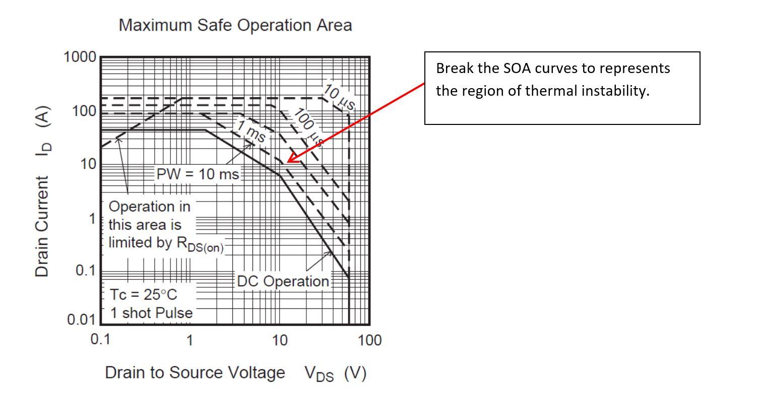
It includes the are of thermal instability, indicated by the breakpoints on the lines. This is fairly reliable.
If the SOA curve looks like this:
This datasheet was generated before the interest in thermal instability or the part does not suffer from thermal instability. This is tough to decide and the parts have to be tested.
I would be very cautious of the datasheets so no thermal instability. I would not assume that company S is better than company I.
Testing
I have done some testing to verify SOA curves on a few MOSFETs. Here are some of the results:
Testing the IRFP250
I have not tested the IRFP250 (N). It would be interesting to see how it performed at 40W and 150V.
(May be if I get a minute or two and I want sacrifice a few MOSFETs)
My gut tells me that it should perform reasonably well. It is an older part, it has not really being optimized for switching. I don't know if has been 'improved' by die shrinks which would reduce its reliability in the linear region.
Regards,
Jay_Diddy_B
-
What are your opinions on GW Instek electronic loads like PEL-3000E?
http://www.gwinstek.com/en-global/products/Electronic_Loads/DC_Electronic_Loads/PEL-3000E
Is it better than Rigol?
GW Instek has been producing DC electronic loads for a long time, there was PEL-300 some time ago.
http://www.gwinstek.ca/products/742/300w-programmable-dc-electronic-load
-
In my Siglent SPD3303D power supply there is the same problem for an otherwise good device: no velocity for the knob and it is even worse, because it doesn't have a numeric input, and if I turn it fast, sometimes it goes even back (maybe they didn't sample it with a high sample rate and a state machine, but used an interrupt for one pin of the quadrature encoder, which you shouldn't do). And firmware update didn't work. I guess they need some more years experience until they get to the level of something like my Agilent scope for the GUI. Hopefully the price doesn't increase then as well.
But this looks like a serious limitation for the battery app. In the video it sounded like it can do only a constant current discharge test in this mode? -
But this looks like a serious limitation for the battery app. In the video it sounded like it can do only a constant current discharge test in this mode?
That sucks, yes. But its something fixable in firmware, which I think they are going to fix because a lot of people will complain. -
But this looks like a serious limitation for the battery app. In the video it sounded like it can do only a constant current discharge test in this mode?
That sucks, yes. But its something fixable in firmware, which I think they are going to fix because a lot of people will complain.
They told me that other discharge modes will be added in a firmware update, but that update was scheduled for the end of last month and it didn't materialize. -
What is wrong with this document?
AND8119 is a 2W bias power supply design, and there is nothing in it about thermal runaway.
Sorry - i've made a typo. AND8199/D would be the right document.
https://www.onsemi.com/pub/Collateral/AND8199-D.PDF -
In my Siglent SPD3303D power supply there is the same problem for an otherwise good device: no velocity for the knob ...
to be honest: i really hate devices with velocity in the knobs.It happens so often that i want to increase some value by a small amount - and when turning just a little bit too much it makes huge steps into an area of damage.
So the rigol-solution (they are using the same principle i.e. in their DG1000Z function generators line) where you can preselect the decimal place where you do your changes is not really a bad one. Sometimes it is annoying too - but you always have full control.
In my opinion the DL3021 is not a really bad device and it is much better in many points than i.e. maynuo, BK or itech devices. But it has some design flaws that may be a showstopper for some people (for me it was the 3,5 MHz oscillation observed... some data that were completely out of spec ... and the huge size of the device compared to its load capabilities). -
It's good if it's implemented well, unfortunately it often isn't.In my Siglent SPD3303D power supply there is the same problem for an otherwise good device: no velocity for the knob ...
to be honest: i really hate devices with velocity in the knobs.It happens so often that i want to increase some value by a small amount - and when turning just a little bit too much it makes huge steps into an area of damage.
-
It's good if it's implemented well, unfortunately it often isn't.In my Siglent SPD3303D power supply there is the same problem for an otherwise good device: no velocity for the knob ...
to be honest: i really hate devices with velocity in the knobs.It happens so often that i want to increase some value by a small amount - and when turning just a little bit too much it makes huge steps into an area of damage.
I've never seen a good implementation (for my needs). -
I have to admit that my confidence in Rigol is severely shaken, the scope i have is nice but clearly they went bananas over scope design as it's the first and most desired product, but can they make anything else properly? maybe not.
-
The heat sink temperature at some 80 C is not such a disaster - they may fix it in future versions. Also the 240 V volts in Australia give the regulator is little more stress than 230 V in Europe.
Otherwise the circuit looks a little odd in some places, but not bad. For the software there are a few more features they might be able to add. What makes my scratch the hata little are the specs for the given HW.
Instead of 200 W, 40 A / 150 V and 0.05% accuracy, the HW looks more like suitable for
400W, 60A / 80 V and 0.2 % accuracy. Still a nice load, but kind of a different model.
If you want real battery testing, one would use a different gear in most cases anyway. More like multi channels and usually lower power / lower voltage.
It might be interesting how good / fast the current read back is. -
If you want real battery testing, one would use a different gear in most cases anyway. More like multi channels and usually lower power / lower voltage.
I concur. The battery tester I've worked on had 80 channels, and much higher accuracy for voltage and current. Capacity testing and coulombic efficiency requires very accurate equipment. This tester is fine to determine, wheter that 5 year old 12V battery is still holding some charge or not, or the new battery you bought has the claimed capacity.It might be interesting how good / fast the current read back is.
You made me take a second look at it.
The shunt is isabellenhütte BVS 0.0005Ohm, which has a typical 50ppm/K tempco, but the 0.0005Ohm version has a typical 70ppm tempco. And the spec for the rigol is 50ppm/K.
And they dont include the tempco of the AFE. No way for it to be within that spec.
They also send 40A through that shunt, so self heating is about a watt. And they give 1000PPM (equivalent of 20K self heating) specification for full scale. I'm sorry, but those accuracy specifications are just not realistic. You cannot just take a number from one datasheet and use that for your specification. In the video Dave measures it out of spec (around 30 minutes). No wonder why. -
In the video Dave measures it out of spec (around 30 minutes). No wonder why.
Well, it is not out of spec. Dave is making the small mistake of assuming that the current readback has the same accuracy than the current setting. But the device does not switch the measurement range when switching the input range - even in the 4A setting range the readback range is still 40A.
Readback accuracy is ±(0.05%+0.05%FS). So the allowed readback reading for 1A would be 0.98A to 1.021A. Dave hat a measurement of 0.9977A - so the device is full within spec.
That the current readback range is not switched down with the current setting range is a shame. One of the real big showstoppers in my opinion for this device (and something that is not software-fixable). None of the big competitors is doing so.
There are so many users of this devices that want to characterize batterys - therefore an exact low current measurement is neccessary. -
You made me take a second look at it.
The shunt is isabellenhütte BVS 0.0005Ohm, which has a typical 50ppm/K tempco, but the 0.0005Ohm version has a typical 70ppm tempco. And the spec for the rigol is 50ppm/K.
And they dont include the tempco of the AFE. No way for it to be within that spec.
They also send 40A through that shunt, so self heating is about a watt. And they give 1000PPM (equivalent of 20K self heating) specification for full scale. I'm sorry, but those accuracy specifications are just not realistic. You cannot just take a number from one datasheet and use that for your specification. In the video Dave measures it out of spec (around 30 minutes). No wonder why.
I agree you can't just take numbers from the datasheet, and that could be what they've done here.
But look at the temperature graph for Manganin, the typical response is 17ppm/K, and worst case is 50. So maybe ~24ppm typical, for the 0.0005 ohm version. Its not unusual to use the typical value and not worst case.
Also, I seriously doubt they have done it here, but they could do a full temperature characterization and calibrate it out in software right? But there is no temperature sensor near that shunt that I see. -
You made me take a second look at it.
The shunt is isabellenhütte BVS 0.0005Ohm, which has a typical 50ppm/K tempco, but the 0.0005Ohm version has a typical 70ppm tempco. And the spec for the rigol is 50ppm/K.
And they dont include the tempco of the AFE. No way for it to be within that spec.
They also send 40A through that shunt, so self heating is about a watt. And they give 1000PPM (equivalent of 20K self heating) specification for full scale. I'm sorry, but those accuracy specifications are just not realistic. You cannot just take a number from one datasheet and use that for your specification. In the video Dave measures it out of spec (around 30 minutes). No wonder why.
I agree you can't just take numbers from the datasheet, and that could be what they've done here.
But look at the temperature graph for Manganin, the typical response is 17ppm/K, and worst case is 50. So maybe ~24ppm typical, for the 0.0005 ohm version. Its not unusual to use the typical value and not worst case.
Also, I seriously doubt they have done it here, but they could do a full temperature characterization and calibrate it out in software right? But there is no temperature sensor near that shunt that I see.QuoteYOU NORMALLY USE MANGANIN® AS RESISTANCE ALLOY IN THE RESISTORS. THE TEMPERATURE COEFFICIENT OF MANGANIN® IS SPECIFIED WITH < ± 10 PPM/K. WHY DO YOU MOSTLY SPECIFY YOUR SMD RESISTORS < ± 50 PPM/K ON THE DATA SHEETS?
I came to trust their specifications and products. It is conservatively specified, 99% of the products will be much better than the specification, but then you get one or two, which isnt. But this is not my only issue. The specification (by rigol) is very very optimistic, and to get similar results, I had to use a magnitude better components. I give you an example. The Agilent 34465A has worse (tempco) specification with a better shunt, on the 1A range. And the Agilent doesn't have the self heating issues with 40A of current. In fact I would bet money on this: It wont be anywhere near the specification at 40A.
For a two-wire, the TC of a component is comprised of the TC of the resistance material (e. g. Manganin®) and the not completely avoidable influence of the supply line or bonding. For that reason we usually specify the TC of a two-wire with < 50 ppm/K.
-
Hi,
Here are extracts from datasheets.
First from the Agilent 6060B load (first class load) we have:
And from the current range on the 34470A DMM (very high quality DMM):
The number is percentage of reading plus percentage of range.
The Rigol DL3021 load specifications are:
Rigol is claiming better accuracy, same temperature coefficient, as the Keysight 34470A on the 10A range.
Jay_Diddy_B
-
Despite the teardown not being a be-all-end-all review, it still begs the question...
Is the rigol DL3021 really so bad that you should not buy it?
Reading through the posts here, this is the impression I get.
I couldn't care less about reverse italic or illuminati buttons looking odd if the basic functionality is okay and no dealbreaker artefacts are present. The oscillations demonstrated in one of the forum videos are worrysome in that department.
The alternatives, in this price category and functionality range we mostly have no-name clones on ebay and the likes of Itech IT8500 series. Comparatively, Rigol has its own support and provides firmware updates. So, what is a good alternative then?
Dave mentions Itech also in the BK prescision 8601 review.
I have been postponing purchasing the BK8601 in hopes that something cheaper but still decent will come along, including support from a known company. Missing the direct readout of Wh is a major omission on BK (for me), this why I have postponed the BK. Sure, there is a workaround but for that money i expect more. The RigolDL3021 was really good news on that part....