Author Topic: Voltage detection curcuit design  (Read 2774 times)

0 Members and 1 Guest are viewing this topic.

Offline PhilippGTopic starter

  • Newbie
  • Posts: 3
  • Country: de
Voltage detection curcuit design
« on: June 15, 2016, 04:52:45 pm »
Hello to everyone.

For a current project, i need to build a circuit that can detect, if the Voltage between to contact points exceeds about 50VDC.
If that is the case, two functions must be achieved:

1. An optocoupler has to give signal to another low-voltage side. For this a have an additional 12V Power-supply.

2. A visible LED has to turn on. The problem here is, that i can not use any other supply-voltage, then the one that i am measuring.

The Measuring-Voltage can range from 0 to 600VDC.
First i want to focus on function number 2.

I have build a circuit that fulfilled these requirements based on an LR8 Voltage-Regulator in the past, but it uses a bunch of components.
Since my functionallity is basically the same as a contact-Voltage-tester, i thought, there must be a simple way to do this.

Unfortunattely, i do not have a voltage-tester to spare, to take it apart and reengineer the circuit.

I tried figuring out something on my own.
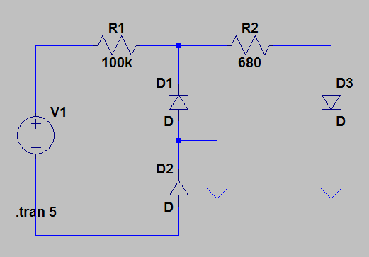
D1 = Zener, ~40V
D2 = Zener, ~6V
D3 = LED
R1 = Current Limiting Resistor
R2 = Current Limit for LED

But with this approach, because of the high input voltage range, either the used energy gets quite high, or i do not have enough energy to drive my led reliably.
Am i missing something?
Or does anybody have a hint on a better solution?
Or maybe someone has a scematic of a contact-voltage-tester?

I would be thankfull for all input!
Greetings,
Philipp
 

Offline Ice-Tea

  • Super Contributor
  • ***
  • Posts: 3190
  • Country: be
    • Freelance Hardware Engineer
Re: Voltage detection curcuit design
« Reply #1 on: June 15, 2016, 06:40:11 pm »
The LR8 uses a bunch of components? Two caps and resistors?

If you want less components, you could use LR645N5  ;)
 

Offline PhilippGTopic starter

  • Newbie
  • Posts: 3
  • Country: de
Re: Voltage detection curcuit design
« Reply #2 on: June 15, 2016, 07:15:44 pm »
The LR8 uses a bunch of components? Two caps and resistors?

If you want less components, you could use LR645N5  ;)

Thank`s for your suggestion.
The LR645N5 with an external FET seems to be a nice option.

In terms of "bunch of components", yes, it doesn`t use that many, but it had quite a large footprint.
Since every Contact-Voltage-Detector seems to do the same task with a smaller footprint, i was wondering, how they were doing it.
 

Offline suicidaleggroll

  • Super Contributor
  • ***
  • Posts: 1453
  • Country: us
Re: Voltage detection curcuit design
« Reply #3 on: June 15, 2016, 07:23:22 pm »
You could use a 47V zener to lift the gate on a FET, which should start to conduct around the 50V mark.  You'd want a second zener to keep the gate voltage in check when the input is at 600V though.  So an Nch FET, two zeners, and a few resistors could do it.
 

Offline PhilippGTopic starter

  • Newbie
  • Posts: 3
  • Country: de
Re: Voltage detection curcuit design
« Reply #4 on: June 15, 2016, 07:47:43 pm »
You could use a 47V zener to lift the gate on a FET, which should start to conduct around the 50V mark.  You'd want a second zener to keep the gate voltage in check when the input is at 600V though.  So an Nch FET, two zeners, and a few resistors could do it.

So you mean something like:


D1: 33V
D3: 51V
 

Online Ian.M

  • Super Contributor
  • ***
  • Posts: 13132
Re: Voltage detection curcuit design
« Reply #5 on: June 15, 2016, 08:34:14 pm »
The main issue is dissipation.  Lets suppose you want 5mA for the indicator LED and optocoupler, and you put them in series to minimise the total current draw.  *IF* you can maintain a constant current all the way up from 50V to 600V, you'll be dissipating 3W @600V.   However if you use a simple resistive dropper, assuming 5V drop across the two LEDs in series + the threshold circuit, it will be a 9K resistor for 5mA @50V with 39.3 watts disipation @ 600V.

You could of course go down to 1mA through the LED and optocoupler, reducing the worst case dissipation in the dropper to 7.9W but that's still a *LOT* of power.   The only way out of that rabbit hole is a heatsinked HV MOSFET as a constant current dropper, but the gate threshold spread means either each unit needs individual calibration or you have to accept a wide spread of currents.

Detection of the 50V threshold and switching the LEDs is relatively simple once you have a stabilised lower voltage to power stuff off, but if you want sharp switching at a well defined threshold, a higher component count is unavoidable.
 

Offline suicidaleggroll

  • Super Contributor
  • ***
  • Posts: 1453
  • Country: us
Re: Voltage detection curcuit design
« Reply #6 on: June 15, 2016, 09:24:30 pm »
You could use a 47V zener to lift the gate on a FET, which should start to conduct around the 50V mark.  You'd want a second zener to keep the gate voltage in check when the input is at 600V though.  So an Nch FET, two zeners, and a few resistors could do it.

So you mean something like:

D1: 33V
D3: 51V

More like the attached.

When Vcc < 47, the gate is pulled to ground, the Nch is off, and the LED is off
When Vcc rises above 47, the first zener starts to conduct and raises the Nch gate to Vcc-47 volts.  The second zener is still off and not doing anything.  When the Nch gate passes Vgs(th), it starts to conduct and the LED turns on
When Vcc rises above 59, the gate hits 12V, and the 12V zener starts to conduct, keeping the gate from going any higher than that.  The value of the resistors around the zeners don't really matter as long as they're not so big that the leakage current through the zeners starts to have a noticeable effect, somewhere around 1M would probably be fine.  As Ian said though, you need to watch how you handle the LED's current limiter.
« Last Edit: June 15, 2016, 09:44:21 pm by suicidaleggroll »
 

Offline Ammar

  • Regular Contributor
  • *
  • Posts: 154
  • Country: au
Re: Voltage detection curcuit design
« Reply #7 on: June 16, 2016, 02:21:34 am »
You could use a resistive divider to step down the voltage by a factor. Then a linear voltage regulator, maybe a 7805 to power a comparator (not sure of the max voltage it can take, maybe try a 7812?). Compare the stepped down voltage to a reference (zener, resistive divider, IC) and use the output of the comparator to drive your LED and opto-coupler.


Share me

Digg  Facebook  SlashDot  Delicious  Technorati  Twitter  Google  Yahoo
Smf