Hello, thank you again for your reply!
Those combo meters have their power supply ground, volt meter ground and amp meter ground all connected together.
Yes, that's what I meant by " indeed the (-) of the meter is tied to the low side of the shunt", sorry if that wasn't clear,
You will probably short the diodes D2, D3 and capacitor C4 by using them.
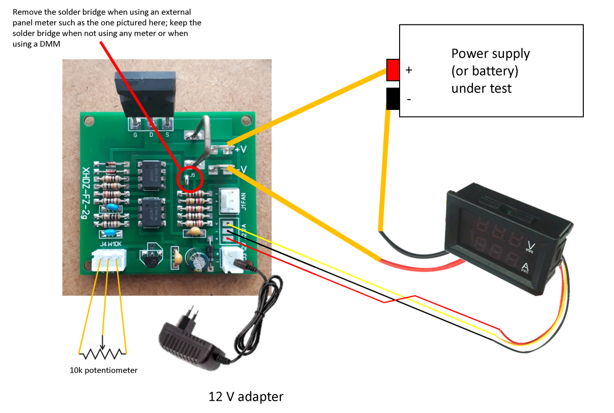
No, that will be fine, because the ground of the DC load is not brought out to J2 (which is the connector made on purpose for an external meter); only the +0.7 V rail, the anode of D3 if you will, is present there. So the panel meter is powered by 12V minus 0.7V, which is fine.
As a picture is often better than many words, maybe this will help other newbies like me in the future:

Here is an example: (video)
thank you for the link though, will save it for later, that may very well be useful for another hobby project.
I spent some time studying the circuit in more detail and playing with this little board at my bench.
One of the questions I had in my previous posts was, why is it so important that this connection is made ? Given that we have a differential amplifier, why couldn't we let (V-) float?

well, I did a bit of homework and this is what I found :
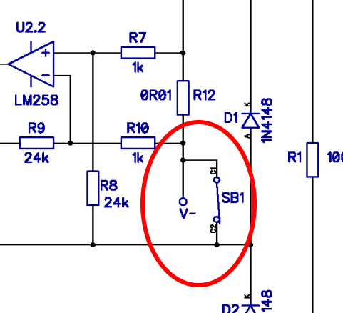
- the current input between (V+) and (V-) will not be truly floating anyways, because of R1 and R2. So when SB1/J5 is left disconnected, there is current flowing from the +0.7 V rail (D3 anode), through R8 and R7 (not desirable), thus increasing the current through R12, which in turn causes measurement errors because the current in the FET is not anymore equal to the current in R12.
- tying (V-) to the +0.7V rail also ensures that the voltage seen by U2.2 stays within the allowed limits
Also, thanks to your help, here are my other conclusions:
- the LM393 is here as you said to ensure that the FET remains off when nothing is connected, preventing current surges,
- contrary to what I was suggesting before, it's not possible to remove D3 and C4 to get rid of the +0.7V rail and to tie the inverting input of the LM393 to ground, because then there is no way its non-inverting input could go below ground, so the comparator never switches and the FET stays on at startup.
- I think D2 is there to clamp the voltage seen at the (+) input of U1 to 0.7V more than its (-) input, even when the load is connected to a fairly high voltage source (the ebay listings claim up to 100V, not sure I would dare though)
- it is necessary to remove the solder bridge J5 (SB1 on my schematic) when using an external meter as pictured, because otherwise the internal current shunt of the panel meter is short-circuited by the solder bridge, which causes huge measurement errors.
does that make sense?
Also, does anyone have a clue about what D1 is doing ?For fun I tortured the load with various combinations of reverse voltages on its inputs (with the current limit of my PSU set very low), and I had a 1R resistor in series with D1 to see if it was passing any current, but I haven't found any situation that would make it conduct.
Thank you everyone and please feel free to comment,
JF