UpdateNow back at it and found the issue.
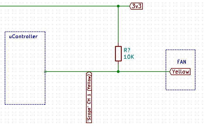
The Hall sensor on the cheap eBay fans (various types) have a very low voltage level output, or if it is 'open collector', not going to GND when the signal has been 'pulled up' to VCC/VDD.1. The reason I am using the 10k pull up to 12v and voltage divider to scale to approx 3v is because the fans are/will be 'Isolated' from the uController. There will probably be a clamping Zener too but it is not shown in the original image.
2. All GNDs for the scope, Fan and components shown share the 12vGND.
3. I am not using PWM for fan control, Just standard switching from the uController at the moment.
4. I am using a MOSFET in a 'high side' switching design for the fan power so that the fan always has a path to GND and keeps EMI down to a minimum.
This shows the position of the scope probes.

Using a Noctua 12v DC Brushless Fan.

A little bit of noise but everything looks good. The scaling of the voltage divider is fine and a good looking waveform. This also works correctly and the uController reads the fan rotations correctly.
A cheap eBay (Chinese) 12v DC Brushless Fan (Using the same setup as before).

You can see the 'Spikes' of the hall sensor output on the DC bias. Very small but
not going to GND!
ggchab Suggested circuit. (thanks!)
and the results ...

no surprise there.
No components ...

and zoomed in to see the waveform

looks usable, maybe with an OpAmp ... but,
every few seconds there is an additional signal being picked up by the hall sensor...

Manually stopping the fan I can see that same 'interference' signal repeat at regular intervals. I have not looked at any cause for this at the moment as it may be a mute point. The Noctua fan does not suffer with the issue. This maybe because the hall sensor signal levels are much stronger/ 'emitter' going to GND, on the Noctua and the 'interference' is in the millivolt range. Maybe it is there but not too noticeable?
My personal conclusion These cheap Chinese fans from eBay are not outputting a very strong (or not going to GND with pull up resistor) or clean signal in comparison to a Noctua. I have tried various models of these
cheap fans that I have lying around and most have low voltage hall sensor output and are picking up additional 'noise'. The noise may not be too much of an issue if it were at least giving a better output.
Obviously I could just buy better quality fans, but I am a little confused why other people are not having the same issues.
I moved to a MOSFET highside fan switching design so that there is a path to GND all of the time for the MOSFET.
I am not using PWM for fan control at the moment either so no noise is being created by that to the hall sensor.
If I want to get this working I guess I could track down what is causing the additional spikes, remove them somehow. If this hall output is indeed 'Open Collector' then I do not understand why, after pulling the signal up to VCC/VDD via a resistor, it does not get the 'emitter' to GND.
This is where it is failing.Additionally, I would also like to learn about removing 'noise' from a signal but I imagine that is a bit of a black art. Any helpful 'novice' info on this subject would be appreciated. At least my LC meter from Japan arriving tomorrow made it through the Typhoon!
I think I will now rebuild the fans on a new clean breadboard and go from there.All suggestions welcome.


