Author Topic: Smoothing Capacitors ???  (Read 19693 times)

0 Members and 3 Guests are viewing this topic.

Offline ChrisGreece52Topic starter

  • Frequent Contributor
  • **
  • Posts: 829
  • Country: gb
  • Electronics Engineer - Hacker - Nerd
Smoothing Capacitors ???
« on: May 09, 2013, 09:37:54 pm »
Hello i made a reasearch about smoothing capacitors and i got more confused.
Questions i got from my reasearch :
1)Does it trim the wave like a diode in an AC circuit ?
2)Why shall anyone use a Smoothing Cap
3)How big should a smoothing capacitor be ?
4)If you change the value (say increase from 1microfarad to 10) what changes in smoothing you will get?
5)Can a smoothing capacitor (big or small) make a perfect wave (completely flat)
6)Can you use capacitor in Bridge rectifiers for better results?
7)Whats the peak to peak ripple that the capacitor forms ?
Thank you.
Source Sites
http://www.learningaboutelectronics.com/Articles/What-is-a-smoothing-capacitor
http://www.radio-electronics.com/info/circuits/diode-rectifier/rectifier-filtering-smoothing-capacitor-circuits.php
 

Offline ChrisGreece52Topic starter

  • Frequent Contributor
  • **
  • Posts: 829
  • Country: gb
  • Electronics Engineer - Hacker - Nerd
Re: Smoothing Capacitors ???
« Reply #1 on: May 09, 2013, 09:39:03 pm »
The second website its very good and offers a great amount of information but those questions are still standing!!!!
 

Offline JackOfVA

  • Supporter
  • ****
  • Posts: 350
  • Country: us
Re: Smoothing Capacitors ???
« Reply #2 on: May 09, 2013, 09:50:19 pm »
Your questions sound exactly like homework questions for an electronics class.
 

Offline c4757p

  • Super Contributor
  • ***
  • Posts: 7799
  • Country: us
  • adieu
Re: Smoothing Capacitors ???
« Reply #3 on: May 09, 2013, 09:50:47 pm »
1)Does it trim the wave like a diode in an AC circuit ?

No. When the incoming AC voltage is above the voltage stored on the capacitor, the capacitor charges through the diode. When it's low, the diode blocks it, and the circuit continues to run off the charge stored in the capacitor in the interim until the next AC peak.

Quote
2)Why shall anyone use a Smoothing Cap

...to smooth.

Quote
3)How big should a smoothing capacitor be ?

The basic equation for a capacitor is I = C * dv/dt. dv/dt just means the rate of change of the voltage, measured in volts/second. You know I (it's the current you are drawing), and you should choose a value for dv/dt that keeps the voltage high enough for your circuit to run in between peaks. For example, if you can afford to lose two volts, and your capacitor is being charged 100 times per second (full-wave rectification at 50 Hz), then the rate of change is 2V*100Hz = 200V/s. Then just solve for C.

Quote
4)If you change the value (say increase from 1microfarad to 10) what changes in smoothing you will get?

I = C * dv/dt. What happens to dv/dt if C increases.

Quote
5)Can a smoothing capacitor (big or small) make a perfect wave (completely flat)

I = C * dv/dt. What would C have to be for dv/dt to be zero?

Quote
6)Can you use capacitor in Bridge rectifiers for better results?

By "better results" do you mean "any results at all"?

Quote
7)Whats the peak to peak ripple that the capacitor forms ?

I = C * dv/dt. dv/dt is the rate of change, so multiply that by the period (divide by the frequency) to get the total change in voltage.
No longer active here - try the IRC channel if you just can't be without me :)
 

Offline c4757p

  • Super Contributor
  • ***
  • Posts: 7799
  • Country: us
  • adieu
Re: Smoothing Capacitors ???
« Reply #4 on: May 09, 2013, 09:54:47 pm »
The second website its very good and offers a great amount of information but those questions are still standing!!!!

If you can't answer at least 1, 3, 4, 5, and 7 from the information in the second website, you need to read it again. And again, if you still don't get it. It's all there. The answers aren't given to you, the understanding of a rectifier circuit is given to you. You then use this understanding to figure out the answers. It's learning.
No longer active here - try the IRC channel if you just can't be without me :)
 

Offline ChrisGreece52Topic starter

  • Frequent Contributor
  • **
  • Posts: 829
  • Country: gb
  • Electronics Engineer - Hacker - Nerd
Re: Smoothing Capacitors ???
« Reply #5 on: May 09, 2013, 10:01:56 pm »
Your questions sound exactly like homework questions for an electronics class.
Thank you but as weird as it seems my source is this forum and the internet in school we are still stuck on electromagnetism and the few things that we learned in school about capacitors are only theoritical (calculating capacitance voltage and its charge when we change something like the distance between the plates or the voltage) and we did some excercises in which the capacitor was in a circuit but nothing more :)
 

Offline free_electron

  • Super Contributor
  • ***
  • Posts: 8550
  • Country: us
    • SiliconValleyGarage
Re: Smoothing Capacitors ???
« Reply #6 on: May 09, 2013, 10:04:07 pm »
Hello i made a reasearch about smoothing capacitors

if you did some REAL research you would know the answers to the following :

1)Does it trim the wave like a diode in an AC circuit ? (which is gibberish anyway .. )
2)Why shall anyone use a Smoothing Cap
3)How big should a smoothing capacitor be ?
4)If you change the value (say increase from 1microfarad to 10) what changes in smoothing you will get?
5)Can a smoothing capacitor (big or small) make a perfect wave (completely flat)
6)Can you use capacitor in Bridge rectifiers for better results?
7)Whats the peak to peak ripple that the capacitor forms ?
Professional Electron Wrangler.
Any comments, or points of view expressed, are my own and not endorsed , induced or compensated by my employer(s).
 

Offline ChrisGreece52Topic starter

  • Frequent Contributor
  • **
  • Posts: 829
  • Country: gb
  • Electronics Engineer - Hacker - Nerd
Re: Smoothing Capacitors ???
« Reply #7 on: May 09, 2013, 10:07:37 pm »
The second website its very good and offers a great amount of information but those questions are still standing!!!!

If you can't answer at least 1, 3, 4, 5, and 7 from the information in the second website, you need to read it again. And again, if you still don't get it. It's all there. The answers aren't given to you, the understanding of a rectifier circuit is given to you. You then use this understanding to figure out the answers. It's learning.
Right but comming here and asking means i already read it (to be honest NOT again and again just 1 time and 1 fast reading ) and did not understand it completely!!!
 

Offline ChrisGreece52Topic starter

  • Frequent Contributor
  • **
  • Posts: 829
  • Country: gb
  • Electronics Engineer - Hacker - Nerd
Re: Smoothing Capacitors ???
« Reply #8 on: May 09, 2013, 10:16:55 pm »
1)Does it trim the wave like a diode in an AC circuit ?

No. When the incoming AC voltage is above the voltage stored on the capacitor, the capacitor charges through the diode. When it's low, the diode blocks it, and the circuit continues to run off the charge stored in the capacitor in the interim until the next AC peak.

Quote
2)Why shall anyone use a Smoothing Cap

...to smooth.

Quote
3)How big should a smoothing capacitor be ?

The basic equation for a capacitor is I = C * dv/dt. dv/dt just means the rate of change of the voltage, measured in volts/second. You know I (it's the current you are drawing), and you should choose a value for dv/dt that keeps the voltage high enough for your circuit to run in between peaks. For example, if you can afford to lose two volts, and your capacitor is being charged 100 times per second (full-wave rectification at 50 Hz), then the rate of change is 2V*100Hz = 200V/s. Then just solve for C.

Quote
4)If you change the value (say increase from 1microfarad to 10) what changes in smoothing you will get?

I = C * dv/dt. What happens to dv/dt if C increases.

Quote
5)Can a smoothing capacitor (big or small) make a perfect wave (completely flat)

I = C * dv/dt. What would C have to be for dv/dt to be zero?

Quote
6)Can you use capacitor in Bridge rectifiers for better results?

By "better results" do you mean "any results at all"?

Quote
7)Whats the peak to peak ripple that the capacitor forms ?

I = C * dv/dt. dv/dt is the rate of change, so multiply that by the period (divide by the frequency) to get the total change in voltage.
Thanks for your answers i got most of it .... but the 3 parts that i did not quite get i colored them red
for the first red section my question is :Given that the dv/dt is stable !!! because i came up with C=I*dt/dv  .... if dt/dv = stable then if i increase the Capacitance C' > C
i get something like
I'*dt/dv(if dt/dv = stable) > I* dt/dv so if i increase the Capacitance the Amperes get increased to .
for the second red part what do you mean by any results at all ??? Bridge rectifier is just 4 diode connected together so that they convert any AC signal to DC (or is this wrong ?) so using a capacitor will help "killing" the small ripples of the conversion (because bridge rectifiers are not perfect) (or am i wrong ).
and for the 3rd part : I just did not quite get that .... (also i am a bit confused with the dt/dv thing that it found in the equation ......)
THANK YOU FOR YOUR HELP (And i hope i am not retarded by not getting some stuff :P )
 

Offline ChrisGreece52Topic starter

  • Frequent Contributor
  • **
  • Posts: 829
  • Country: gb
  • Electronics Engineer - Hacker - Nerd
Re: Smoothing Capacitors ???
« Reply #9 on: May 09, 2013, 10:20:53 pm »
I also made an experiment with a 555 timer circuit and ... when i connected one 1000 uf capacitor to the output (pin 3 --- ground) the led seemed a LOT dimmer!!!
whats that ?? Did i smooth that signal or just did nothing
I think i smoothed it because i think that by adding a cap the larger the cap is the lower the value of I gets .... (source I=C*dt/dv)
 

Offline ChrisGreece52Topic starter

  • Frequent Contributor
  • **
  • Posts: 829
  • Country: gb
  • Electronics Engineer - Hacker - Nerd
Re: Smoothing Capacitors ???
« Reply #10 on: May 09, 2013, 10:24:30 pm »
Hello i made a reasearch about smoothing capacitors

if you did some REAL research you would know the answers to the following :

1)Does it trim the wave like a diode in an AC circuit ? (which is gibberish anyway .. )
2)Why shall anyone use a Smoothing Cap
3)How big should a smoothing capacitor be ?
4)If you change the value (say increase from 1microfarad to 10) what changes in smoothing you will get?
5)Can a smoothing capacitor (big or small) make a perfect wave (completely flat)
6)Can you use capacitor in Bridge rectifiers for better results?
7)Whats the peak to peak ripple that the capacitor forms ?
Number 2 was just ..... (sorry) but when i found the formula (I=C*dt/dv) i did not quite get the dt/dv part...
As for number 5 i HAD NO IDEA really and i was kinda excited that i learned something like that.
and lastly 6 which i still dont get it .... and number 7 which i dont still get the peak to peak ripple part.....
 

Offline c4757p

  • Super Contributor
  • ***
  • Posts: 7799
  • Country: us
  • adieu
Re: Smoothing Capacitors ???
« Reply #11 on: May 09, 2013, 10:27:33 pm »
Thanks for your answers i got most of it .... but the 3 parts that i did not quite get i colored them red
for the first red section my question is :Given that the dv/dt is stable !!! because i came up with C=I*dt/dv  .... if dt/dv = stable then if i increase the Capacitance C' > C
i get something like
I'*dt/dv(if dt/dv = stable) > I* dt/dv so if i increase the Capacitance the Amperes get increased to .

I'm not even going to attempt this one until you rewrite it. I have no idea what you're getting at.

Quote
for the second red part what do you mean by any results at all ??? Bridge rectifier is just 4 diode connected together so that they convert any AC signal to DC (or is this wrong ?) so using a capacitor will help "killing" the small ripples of the conversion (because bridge rectifiers are not perfect) (or am i wrong ).

A bridge rectifier outputs pulsed DC. It is nowhere near "perfect" - the voltage drops all the way to zero! It just doesn't go negative, which is why it's not considered AC - current only flows forwards, even if it doesn't always flow at all. That's why you need a capacitor to hold charge while the voltage is too low. If you don't use a capacitor at all you won't have proper DC.

Quote
and for the 3rd part : I just did not quite get that .... (also i am a bit confused with the dt/dv thing that it found in the equation ......)

You have I and C, so calculate dv/dt. (dv/dt isn't as confusing as it looks. It just means the rate of change of the voltage - if you plot the voltage, it's how steep the plot is. "dv/dt" means "difference in voltage / difference in time", sort of.) Then divide by the frequency to figure out the total change.

I also made an experiment with a 555 timer circuit and ... when i connected one 1000 uf capacitor to the output (pin 3 --- ground) the led seemed a LOT dimmer!!!
whats that ?? Did i smooth that signal or just did nothing

The pulses from the 555 are passing through the capacitor, essentially. It's like if you put a capacitor directly on a transformer without a diode. Think about it - on the edge of a pulse, the voltage changes very quickly, so dv/dt is very high. This means that C * dv/dt is very high, so the capacitor conducts a large current. Putting a capacitor directly on a square wave is pretty much like shorting it to ground.
« Last Edit: May 09, 2013, 10:32:09 pm by c4757p »
No longer active here - try the IRC channel if you just can't be without me :)
 

Offline ChrisGreece52Topic starter

  • Frequent Contributor
  • **
  • Posts: 829
  • Country: gb
  • Electronics Engineer - Hacker - Nerd
Re: Smoothing Capacitors ???
« Reply #12 on: May 09, 2013, 10:49:47 pm »
Thanks for your answers i got most of it .... but the 3 parts that i did not quite get i colored them red
for the first red section my question is :Given that the dv/dt is stable !!! because i came up with C=I*dt/dv  .... if dt/dv = stable then if i increase the Capacitance C' > C
i get something like
I'*dt/dv(if dt/dv = stable) > I* dt/dv so if i increase the Capacitance the Amperes get increased to .

I'm not even going to attempt this one until you rewrite it. I have no idea what you're getting at.

Quote
for the second red part what do you mean by any results at all ??? Bridge rectifier is just 4 diode connected together so that they convert any AC signal to DC (or is this wrong ?) so using a capacitor will help "killing" the small ripples of the conversion (because bridge rectifiers are not perfect) (or am i wrong ).

A bridge rectifier outputs pulsed DC. It is nowhere near "perfect" - the voltage drops all the way to zero! It just doesn't go negative, which is why it's not considered AC - current only flows forwards, even if it doesn't always flow at all. That's why you need a capacitor to hold charge while the voltage is too low. If you don't use a capacitor at all you won't have proper DC.

Quote
and for the 3rd part : I just did not quite get that .... (also i am a bit confused with the dt/dv thing that it found in the equation ......)

You have I and C, so calculate dv/dt. (dv/dt isn't as confusing as it looks. It just means the rate of change of the voltage - if you plot the voltage, it's how steep the plot is. "dv/dt" means "difference in voltage / difference in time", sort of.) Then divide by the frequency to figure out the total change.

I also made an experiment with a 555 timer circuit and ... when i connected one 1000 uf capacitor to the output (pin 3 --- ground) the led seemed a LOT dimmer!!!
whats that ?? Did i smooth that signal or just did nothing

The pulses from the 555 are passing through the capacitor, essentially. It's like if you put a capacitor directly on a transformer without a diode. Think about it - on the edge of a pulse, the voltage changes very quickly, so dv/dt is very high. This means that C * dv/dt is very high, so the capacitor conducts a large current. Putting a capacitor directly on a square wave is pretty much like shorting it to ground.
Again thank you there are my answers
Quote
The pulses from the 555 are passing through the capacitor, essentially. It's like if you put a capacitor directly on a transformer without a diode. Think about it - on the edge of a pulse, the voltage changes very quickly, so dv/dt is very high. This means that C * dv/dt is very high, so the capacitor conducts a large current. Putting a capacitor directly on a square wave is pretty much like shorting it to ground.
WELL CRAP!!! :P
(also you are telling me that theres NO way to smooth a signal from a 555 timer chip ???But if the fall time was larger (then the dv/dt would be smaller) the capacitor could effect the wave?)
Quote
A bridge rectifier outputs pulsed DC. It is nowhere near "perfect" - the voltage drops all the way to zero! It just doesn't go negative, which is why it's not considered AC - current only flows forwards, even if it doesn't always flow at all. That's why you need a capacitor to hold charge while the voltage is too low. If you don't use a capacitor at all you won't have proper DC.
Thank you that solves another quesions i had (but i have long forgoten) about my 9 volt supply ....  it has a capacitor inside expect from the diodes and i did not know what that was!!!

Quote
I'm not even going to attempt this one until you rewrite it. I have no idea what you're getting at.
Sorry for that ... i suck at explaining :D ill make it as clear as i can :
I meant that to calculate the effects if the capacitor the dv/dt sould be stable because.
If we have a capacitor (C1) and stable I (A) and stable dv/dt(V/S) (all things stable except from (or for i dont know) the capacitor) and we then changed the value of the cap .... (C2>C1) and all other things stable (I=A) and (dv/dt=V/S) .... the formula that would came out of this would ...........
nevermind.... i made the calculation and i gone nowhere.... i came up with this ...
C1>C2 <=> I*dt/dv > I*dt/dv ..... IT DOES NOT MAKE ANY SENSEEEE .... i am confused....
 

Offline ChrisGreece52Topic starter

  • Frequent Contributor
  • **
  • Posts: 829
  • Country: gb
  • Electronics Engineer - Hacker - Nerd
Re: Smoothing Capacitors ???
« Reply #13 on: May 09, 2013, 10:51:48 pm »
What can i build so i can experiment with smoothing caps ???
 

Offline c4757p

  • Super Contributor
  • ***
  • Posts: 7799
  • Country: us
  • adieu
Re: Smoothing Capacitors ???
« Reply #14 on: May 09, 2013, 11:01:50 pm »
WELL CRAP!!! :P
(also you are telling me that theres NO way to smooth a signal from a 555 timer chip ???But if the fall time was larger (then the dv/dt would be smaller) the capacitor could effect the wave?)

Well, you could use an actual rectifier (with diode) - but why would you want to do that?

Edit: If by "smooth" you mean "average" (that is, if it's at 5V half the time and at 0V half the time, you get 2.5V), you can use a low-pass filter to do this. The output will be high impedance, so you'll need to then use an op amp to buffer it.

Quote
Sorry for that ... i suck at explaining :D

Don't feel too bad. Just remember, as this guy says: "There are no stupid questions, only stupid people!"


(Just kidding...)

Quote
ill make it as clear as i can :
I meant that to calculate the effects if the capacitor the dv/dt sould be stable because.
If we have a capacitor (C1) and stable I (A) and stable dv/dt(V/S) (all things stable except from (or for i dont know) the capacitor) and we then changed the value of the cap .... (C2>C1) and all other things stable (I=A) and (dv/dt=V/S) .... the formula that would came out of this would ...........
nevermind.... i made the calculation and i gone nowhere.... i came up with this ...
C1>C2 <=> I*dt/dv > I*dt/dv ..... IT DOES NOT MAKE ANY SENSEEEE .... i am confused....

dv/dt isn't going to be "stable", it's the steepness of the ripple voltage and is determined by the capacitor. I is roughly stable, because it's the current drawn by the circuit. Therefore, if C increases, dv/dt decreases.

Of course, this is all a bit of an approximation. For a resistive load, a DC-DC converter or some other types of load, the current will change slightly as the voltage ripples. Also, this assumes that the capacitor charges instantly, which it does not. Still, it's a useful approximation.
« Last Edit: May 09, 2013, 11:21:21 pm by c4757p »
No longer active here - try the IRC channel if you just can't be without me :)
 

Offline ChrisGreece52Topic starter

  • Frequent Contributor
  • **
  • Posts: 829
  • Country: gb
  • Electronics Engineer - Hacker - Nerd
Re: Smoothing Capacitors ???
« Reply #15 on: May 09, 2013, 11:33:18 pm »
WELL CRAP!!! :P
(also you are telling me that theres NO way to smooth a signal from a 555 timer chip ???But if the fall time was larger (then the dv/dt would be smaller) the capacitor could effect the wave?)

Well, you could use an actual rectifier (with diode) - but why would you want to do that?

Edit: If by "smooth" you mean "average" (that is, if it's at 5V half the time and at 0V half the time, you get 2.5V), you can use a low-pass filter to do this. The output will be high impedance, so you'll need to then use an op amp to buffer it.

Quote
Sorry for that ... i suck at explaining :D

Don't feel too bad. Just remember, as this guy says: "There are no stupid questions, only stupid people!"


(Just kidding...)

Quote
ill make it as clear as i can :
I meant that to calculate the effects if the capacitor the dv/dt sould be stable because.
If we have a capacitor (C1) and stable I (A) and stable dv/dt(V/S) (all things stable except from (or for i dont know) the capacitor) and we then changed the value of the cap .... (C2>C1) and all other things stable (I=A) and (dv/dt=V/S) .... the formula that would came out of this would ...........
nevermind.... i made the calculation and i gone nowhere.... i came up with this ...
C1>C2 <=> I*dt/dv > I*dt/dv ..... IT DOES NOT MAKE ANY SENSEEEE .... i am confused....

dv/dt isn't going to be "stable", it's the steepness of the ripple voltage and is determined by the capacitor. I is roughly stable, because it's the current drawn by the circuit. Therefore, if C increases, dv/dt decreases.

Of course, this is all a bit of an approximation. For a resistive load, a DC-DC converter or some other types of load, the current will change slightly as the voltage ripples. Also, this assumes that the capacitor charges instantly, which it does not. Still, it's a useful approximation.

Thanks i got everything !!! but another thing you said
Quote
Also, this assumes that the capacitor charges instantly, which it does not. Still, it's a useful approximation.
Do these microseconds really count ?
 

Offline ChrisGreece52Topic starter

  • Frequent Contributor
  • **
  • Posts: 829
  • Country: gb
  • Electronics Engineer - Hacker - Nerd
Re: Smoothing Capacitors ???
« Reply #16 on: May 09, 2013, 11:35:08 pm »
as for the low pass filter .. afrotechmods did a great video about these filters
 

Offline c4757p

  • Super Contributor
  • ***
  • Posts: 7799
  • Country: us
  • adieu
Re: Smoothing Capacitors ???
« Reply #17 on: May 09, 2013, 11:36:01 pm »
Thanks i got everything !!! but another thing you said
Quote
Also, this assumes that the capacitor charges instantly, which it does not. Still, it's a useful approximation.
Do these microseconds really count ?

No. This approximation will actually end up choosing a capacitor that is slightly larger than what you need, never too small. I'd actually like to explain that a bit better - give me a minute to draw up a quick plot.
No longer active here - try the IRC channel if you just can't be without me :)
 

Offline ChrisGreece52Topic starter

  • Frequent Contributor
  • **
  • Posts: 829
  • Country: gb
  • Electronics Engineer - Hacker - Nerd
Re: Smoothing Capacitors ???
« Reply #18 on: May 09, 2013, 11:43:31 pm »
Thanks i got everything !!! but another thing you said
Quote
Also, this assumes that the capacitor charges instantly, which it does not. Still, it's a useful approximation.
Do these microseconds really count ?

No. This approximation will actually end up choosing a capacitor that is slightly larger than what you need, never too small. I'd actually like to explain that a bit better - give me a minute to draw up a quick plot.
Thank you i get it finally ... LOW and HIGH pass filter are my next targets!!!
 

Offline c4757p

  • Super Contributor
  • ***
  • Posts: 7799
  • Country: us
  • adieu
Re: Smoothing Capacitors ???
« Reply #19 on: May 09, 2013, 11:46:11 pm »
OK, sorry for the slightly messy hand drawing. Nothing too complicated, I just want to make sure you see this. On the top (true) graph, the capacitor takes longer to charge, so the discharge is shorter. On the second, it charges instantly, so it takes has to be able to discharge for longer. This means you would calculate a bigger capacitance than what you actually need.
No longer active here - try the IRC channel if you just can't be without me :)
 

Offline ChrisGreece52Topic starter

  • Frequent Contributor
  • **
  • Posts: 829
  • Country: gb
  • Electronics Engineer - Hacker - Nerd
Re: Smoothing Capacitors ???
« Reply #20 on: May 09, 2013, 11:54:09 pm »
AAAHHH theres always something hidding into the detail :P thank you so much for your help !!!!
 

Offline mariush

  • Super Contributor
  • ***
  • Posts: 5135
  • Country: ro
  • .
Re: Smoothing Capacitors ???
« Reply #21 on: May 09, 2013, 11:55:14 pm »
Here's as simple as possible explanation...

Let's say you have a transformer that converts mains AC voltage to lower AC voltage :


The output of the transformer is still AC but the peaks are lower, on both positive and negative sides.

When you convert AC voltage to DC voltage, you have to make everything below the 0 line disappear, and this happens when you use diodes to rectify the signal.

If you use a single diode, that's called half wave rectification and the output will look like this:
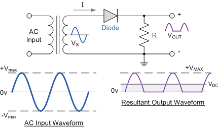


You can see that at the output, you only have voltage when the AC voltage of the transformer was going above the 0 line. The problem is that for half the time, you have 0 voltage on the output because when the AC wave on the transformer is below 0, the diode blocks it.

With full wave rectification, you manage to flip that negative AC voltage segment and have it on the DC output :


But notice that because the AC output is a sine wave, the voltage will climb up all the way to a peak then slowly go down to 0 and than the process repeats itself. With full wave rectification you have a number of "pulses" that's twice the value of your mains frequency (50Hz in Greece afaik)

This output is still considered DC voltage, but it's not like the voltage you're used to, for example by measuring batteries.

For this DC output to be actually usable, you have to add a capacitor there to charge up with energy when a pulse comes and goes all the way to the top, and as the pulse starts to go down towards 0, the capacitor's job is to fill up that space, to resist and keep the voltage up to that peak value for as long as possible.
The more capacity, the more time the capacitor can provide that difference of energy that's no longer provided by the rectified AC wave.
You call it smoothing capacitor because it smooths out the DC ouput, by providing energy for the moments when the rectified AC wave is low.

You can't get the DC wave perfectly smooth, but you can get close enough:


Now again, a capacitor stores energy. If you demand little amount of current, the capacitor discharges slower. If you demand a lot of current, the capacitor discharges faster, because you take out a lot of energy from it.
That's why you have in that formula the current (I) and dv/dt  and that's why the more current you pull, the bigger the dv/dt is, meaning  the more current you need, the faster the voltage goes down within a period of time and the dc output will have more pronounced /\/\/\/\/\/\/\ output.

 
Watch this:


Offline c4757p

  • Super Contributor
  • ***
  • Posts: 7799
  • Country: us
  • adieu
Re: Smoothing Capacitors ???
« Reply #22 on: May 10, 2013, 12:01:42 am »
Well, don't those just make my little sketch look embarrassing!  :-[  :)
No longer active here - try the IRC channel if you just can't be without me :)
 

Offline ChrisGreece52Topic starter

  • Frequent Contributor
  • **
  • Posts: 829
  • Country: gb
  • Electronics Engineer - Hacker - Nerd
Re: Smoothing Capacitors ???
« Reply #23 on: May 10, 2013, 12:03:13 am »
Here's as simple as possible explanation...

Let's say you have a transformer that converts mains AC voltage to lower AC voltage :


The output of the transformer is still AC but the peaks are lower, on both positive and negative sides.

When you convert AC voltage to DC voltage, you have to make everything below the 0 line disappear, and this happens when you use diodes to rectify the signal.

If you use a single diode, that's called half wave rectification and the output will look like this:


You can see that at the output, you only have voltage when the AC voltage of the transformer was going above the 0 line. The problem is that for half the time, you have 0 voltage on the output because when the AC wave on the transformer is below 0, the diode blocks it.

With full wave rectification, you manage to flip that negative AC voltage segment and have it on the DC output :


But notice that because the AC output is a sine wave, the voltage will climb up all the way to a peak then slowly go down to 0 and than the process repeats itself. With full wave rectification you have a number of "pulses" that's twice the value of your mains frequency (50Hz in Greece afaik)

This output is still considered DC voltage, but it's not like the voltage you're used to, for example by measuring batteries.

For this DC output to be actually usable, you have to add a capacitor there to charge up with energy when a pulse comes and goes all the way to the top, and as the pulse starts to go down towards 0, the capacitor's job is to fill up that space, to resist and keep the voltage up to that peak value for as long as possible.
The more capacity, the more time the capacitor can provide that difference of energy that's no longer provided by the rectified AC wave.
You call it smoothing capacitor because it smooths out the DC ouput, by providing energy for the moments when the rectified AC wave is low.

You can't get the DC wave perfectly smooth, but you can get close enough:


Now again, a capacitor stores energy. If you demand little amount of current, the capacitor discharges slower. If you demand a lot of current, the capacitor discharges faster, because you take out a lot of energy from it.
That's why you have in that formula the current (I) and dv/dt  and that's why the more current you pull, the bigger the dv/dt is, meaning  the more current you need, the faster the voltage goes down within a period of time and the dc output will have more pronounced /\/\/\/\/\/\/\ output.

 
Watch this:


Thanks for your information
I read everything and understood everything (mindblowing huh :D ) but the video.... its 39 minutes ill watch it tomorrow gotta go to bed (its 3:10 AM in Greece) :P
Anyway thank you so much!!!
 

Offline c4757p

  • Super Contributor
  • ***
  • Posts: 7799
  • Country: us
  • adieu
Re: Smoothing Capacitors ???
« Reply #24 on: May 10, 2013, 12:05:26 am »
ill watch it tomorrow gotta go to bed (its 3:10 AM in Greece) :P

Ah, you've only got a couple hours until morning, you can do it!  ^-^
No longer active here - try the IRC channel if you just can't be without me :)


Share me

Digg  Facebook  SlashDot  Delicious  Technorati  Twitter  Google  Yahoo
Smf