Good afternoon electro-peeps.
Complete noob here and trying to learn.
I have found a jellybean-parts relaxation oscillator circuit, and I would like to alter it to suit my purposes. I'm hoping someone could check my idea over and let me know if I have completely misunderstood.
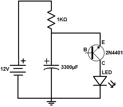
Here is the original circuit.

In this example, the capacitor voltage rises until it and the DC supply have a combined voltage greater than the break-down value of the transistor. In the working examples of this circuit that I've seen, there was no gain in voltage delivered to the LED.
The LED is switched on, however as the capacitor discharges, the voltage falls below the transistor's breakdown once again and so the current no longer flows through that path. Rinse and repeat.
I am proposing to make the following changes.
1) Replace the transistor with a zener diode.
2) Have a zener diode of a value much higher than the DC supply, and a capacitor with a voltage rating at least equal to the DC supply, such that the voltage rises like in a voltage-doubler and is finally released when the zener permits.
3) to facilitate this, I'd insert a blocking diode between the DC supply and that first resistor.
4) No LED
My aim is to take a 130v smooth DC supply that's already in my device and end up with a pulsed DC voltage of 200v (peak) or greater to run an electroluminscent display. I'm guessing I could have the display in parallel after the zener, because electroluminescent displays act as a capacitor and only work on changing voltages.
Obviously, I'd have to change the resistor and capacitor values to get the pulse to the correct Hz, but that's easy enough.
Assuming I do my maths right, does the principle work? And I get a voltage booster and oscillator all-in-one?
Thanks for any help in advance
