Author Topic: Schmitt-Trigger Inverter Oscillating  (Read 2875 times)

0 Members and 3 Guests are viewing this topic.

Offline rHermesTopic starter

  • Contributor
  • Posts: 19
  • Country: no
Schmitt-Trigger Inverter Oscillating
« on: January 02, 2021, 12:30:48 pm »
Intro

Disclaimer: I’m very new to electronics and have only had a scope for a few days, please bear with me ;)

In order to learn more about electronics, I’ve ordered a lot of ICs from AliExpress and I’m just playing around with them. This question is about some weird behavior I’ve seen when playing with the SN74HC14 Hex Schmitt-Trigger Inverter(Link is to the datasheet).

The goal of the exercise was simply to get the IC working and observe it with my scope.

I’m doing these experiments on a breadboard and powering the circuit with a HiLetgo Breadboard power supply module set to 5v.


Problem 1: Oscillating input

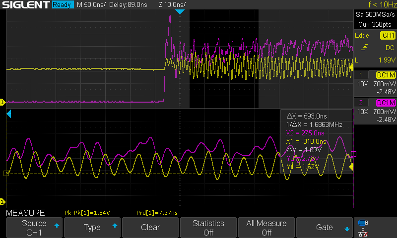
The first problem I observed was that the input and output would oscillate when the Schmitt-Trigger changed levels.

The setup used looks like this:
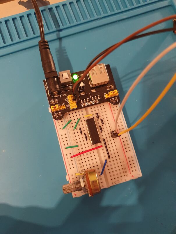


I’ve connected all unused inputs to ground, like the datasheet recommends. I’m using a potentiometer to control the voltage going into the 1A pin. The yellow jumper cable goes to the yellow channel probe on my scope and the white goes to the purple channel. The black and brown channel goes to ground connections on the probes. (The red connector on the middle of the breadboard is not doing anything in this picture, it will come into play later)

With this setup, I start up my oscilloscope(SDS1104X-E) and I see this, which is expected:


The problem comes when I start adjusting the potentiometer, and the Schmitt-Trigger changes levels:
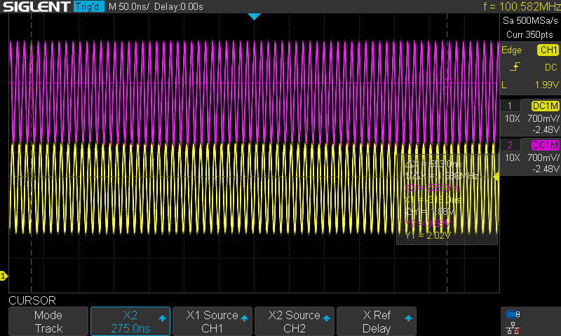
and and
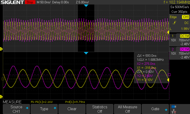
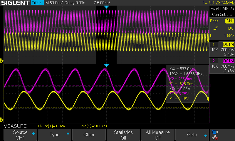
It doesn’t happen all the time, but when it happens, it will get stuck in it. I can then move the input up and down within a range and it will stay oscillation. If I move it too much either way the oscillation will break and the output goes either low or high.

Going from high to low on input and getting oscillation:
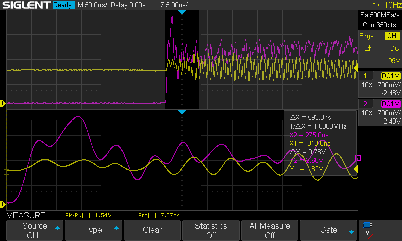
and
Going from low to high without oscillation:
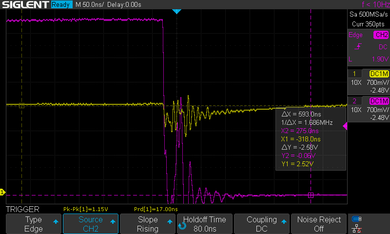


And another example of oscillation:
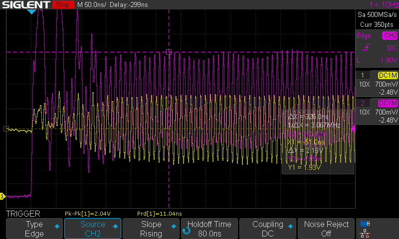


There is some going up and down there too, but it resolves itself.

My question here is really how can the input start oscillating? It is not connected to the output in any other way than the scope probes.

My solution to this has been to attach a capacitor to the input or the output. This dampens the oscillations a bit and so it doesn’t enter that state.

Here is the setup for adding a capacitor the input:
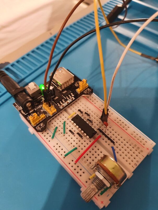

And here is the setup for adding the capacitor to the output:
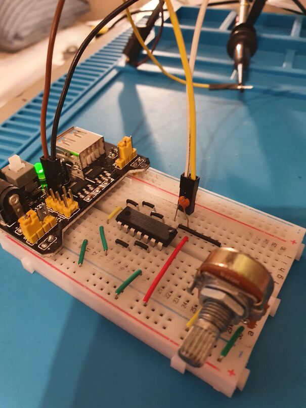

The capacitor needs to be of a certain capacitance to avoid the oscillation. Through manual binary search, I found that when attached to the input it oscillates at 10pF, it wobbles a bit at 15pF and 18pF, but it never happens at 22pF. When attached to the output it oscillates at 30pF, wobbles at 33pF and it never happens at 39pF.

Here is an output of a switch from high to low with a 22pF on the input:
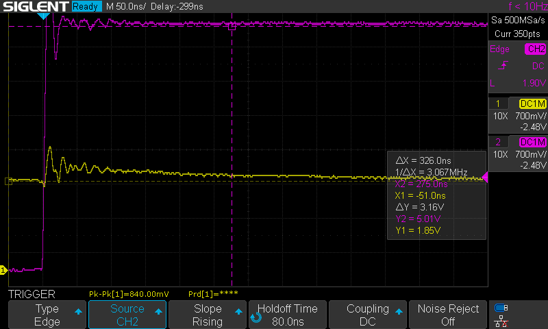

Here is an output of a switch from high to low with a 39pF on the output:
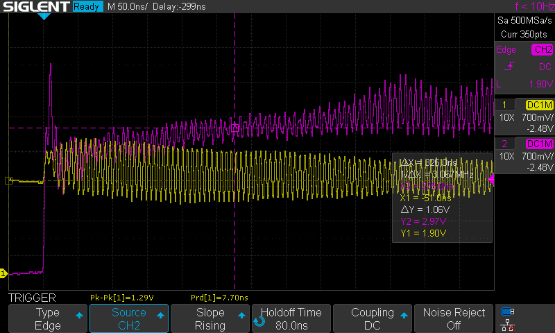

and a switch from low to high:
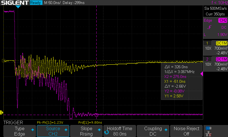

The first waveform was a bit longer than it used to on the input, it usually “resolves” faster, but the two results are reproducible. Multiple runs with triggers repeated these two patterns every time.

My question for this is why is the switch so much cleaner when the capacitor is on the input, even though it’s smaller than the one we put on the output?

Problem 2: No propagation delay when feeding one output into an input

This is something I tried for fun, which is to connect the output of one of the pins on the IC to another input on the same IC. The setup looks like this:
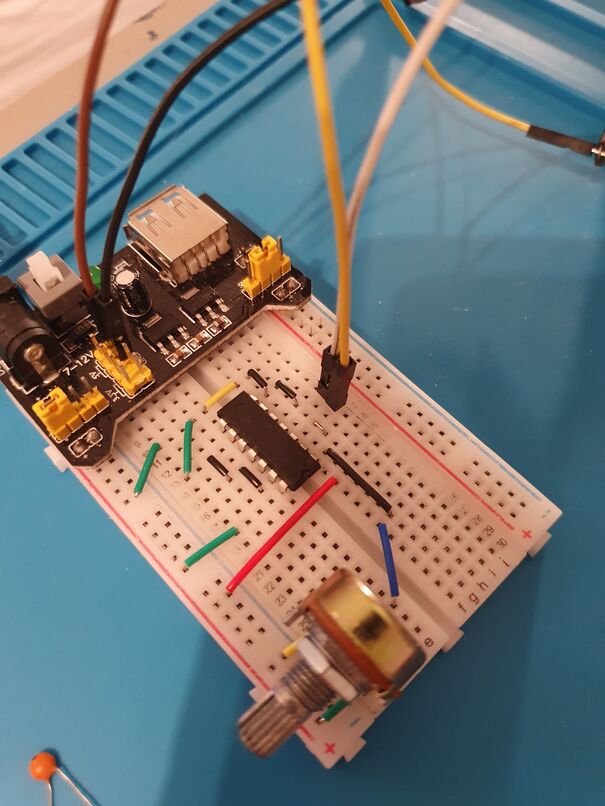

The oscilloscope setup is the same as last time, so this time the yellow line will be the output of the first Schmitt-trigger inverter and the purple line be the output of the second Schmitt-Trigger inverter.

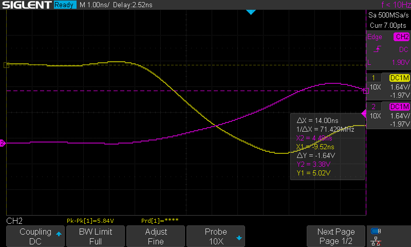
When I turn it around I get no oscillation like before, but when using a trigger, I see that there is some. Here is for low to high:
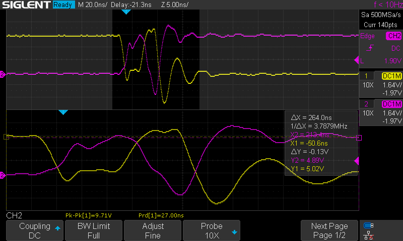

and for high to low:
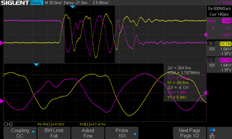

There is some oscillation here, but it dies of quickly. I don’t know why this is, but my real question is: Why does it seem like they both change levels at the same time?

If we look closely:

It looks like they both start changing at the same time. Shouldn’t there be a propagation delay between the input going low and the purple going high?

To test this, I setup another SN74HC14, with identical setup as the first circuit, except that I connected the input of the new SN74HC14 to the output of the first. Here is a picture of the setup:
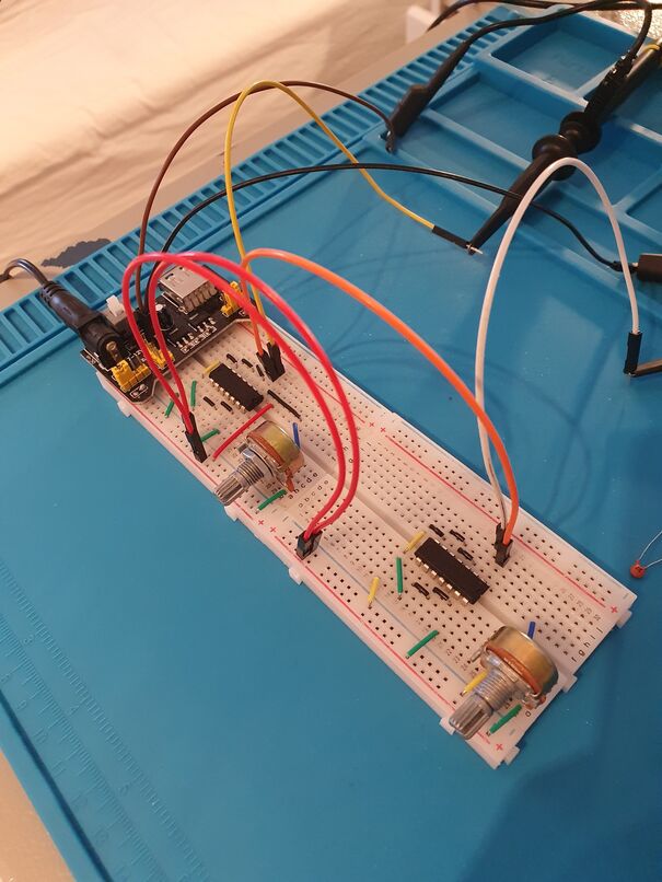

Now the output from here:
and
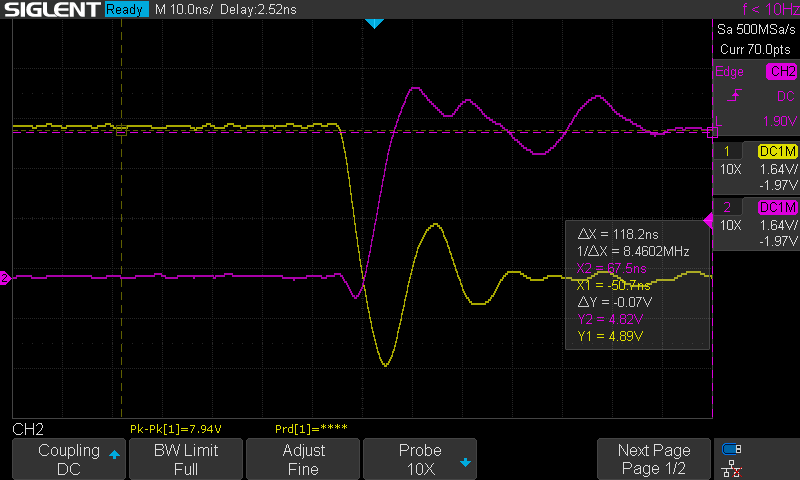
and a zoom in:
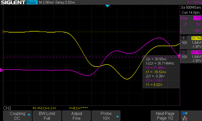

The zoom in isn’t the best, but from the three pictures I’m not sure if I see any propagation delay at all, here either. Am I just measuring this wrong or? Do I need 3 channels and a faster input to really make this measurement?
 

Offline Wallace Gasiewicz

  • Super Contributor
  • ***
  • Posts: 1299
  • Country: us
Re: Schmitt-Trigger Inverter Oscillating
« Reply #1 on: January 02, 2021, 01:02:42 pm »
There is another current post where a comparator is oscillating at 110 MHZ. Comparators contain Schmitt.
Just because I am lazy, please tell me what frequency your setup is oscillating at.
 

Offline rHermesTopic starter

  • Contributor
  • Posts: 19
  • Country: no
Re: Schmitt-Trigger Inverter Oscillating
« Reply #2 on: January 02, 2021, 01:06:43 pm »
There is another current post where a comparator is oscillating at 110 MHZ. Comparators contain Schmitt.
Just because I am lazy, please tell me what frequency your setup is oscillating at.

The frequency is listed on the top right of the screenshots from the first trial. It's 100MHz. Even if they contain comperators, isn't this the exact behavior a Schmitt triggers are supposed to prevent? And how does the output affect the input into oscillating too?
 

Offline Gyro

  • Super Contributor
  • ***
  • Posts: 9804
  • Country: gb
Re: Schmitt-Trigger Inverter Oscillating
« Reply #3 on: January 02, 2021, 01:14:49 pm »
The first thing you are missing is a decoupling capacitor on the supply to the IC. It is always important, but particularly so on a solderless breadboard. Try a 100nF ceramic wire as closely as possible between the VCC and GND pins. Also make sure your ground signal runs as short as possible back to the supply.

It is important to get the basics right before getting tied up in loads of screen captures.
Best Regards, Chris
 

Offline rHermesTopic starter

  • Contributor
  • Posts: 19
  • Country: no
Re: Schmitt-Trigger Inverter Oscillating
« Reply #4 on: January 02, 2021, 01:24:22 pm »
The first thing you are missing is a decoupling capacitor on the supply to the IC. It is always important, but particularly so on a solderless breadboard. Try a 100nF ceramic wire as closely as possible between the VCC and GND pins. Also make sure your ground signal runs as short as possible back to the supply.

It is important to get the basics right before getting tied up in loads of screen captures.
I tried to attach a 100nF ceramic capacitor and had to join them with a jumper cable, because the legs aren't long enough. This made no difference. Same with trying to shorten the distance from ground to the supply with a jumper cable. I can see the decoupling capacitor affecting the stability of the input, but why is the signal run back to the power supply important?
 

Offline Gyro

  • Super Contributor
  • ***
  • Posts: 9804
  • Country: gb
Re: Schmitt-Trigger Inverter Oscillating
« Reply #5 on: January 02, 2021, 01:35:59 pm »
I tried to attach a 100nF ceramic capacitor and had to join them with a jumper cable, because the legs aren't long enough. This made no difference. Same with trying to shorten the distance from ground to the supply with a jumper cable. I can see the decoupling capacitor affecting the stability of the input, but why is the signal run back to the power supply important?

The problem is that you have lots of 'long' (in inductive terms) jumper wires on a device which, as you have shown, is capable of running at 100MHz. This inductance means that unless everything is closely referenced to a common ground (the GND pin on the IC) transient currents from the outputs switching effectively become superimposed on the signals going to the inputs, causing instability that can overcome even a Schmitt input. Putting the decoupling capacitor on the end of a jumper cable is effectively putting an inductor in series with it which reduces its effectiveness at 100MHz (or more properly, the rise and fall times of a few ns).

It may look as if you have no load on the IC output to create current transients, but even the scope probe input capacitance can pose a significant load at fast rise and fall times (of the order of 100-150 ohms).


EDIT: try soldering 20mm of wire to one leg of the capacitor so that you can plug it directly across the IC.
« Last Edit: January 02, 2021, 01:42:42 pm by Gyro »
Best Regards, Chris
 

Offline rHermesTopic starter

  • Contributor
  • Posts: 19
  • Country: no
Re: Schmitt-Trigger Inverter Oscillating
« Reply #6 on: January 02, 2021, 03:16:00 pm »
I tried with an 1uF electrolytic capacitor which has long enough legs that I can place it across the IC and it did not fix the problem.

Also, I don't get your explanation about the GND pin on the IC. None of the outputs are connected to the ground, so how could that affect it? I haven't really looked at inductors yet, so there might be something obvious I'm missing here

Also do you have an answer for the lack of a propagation delay in the second part of the question?
 

Offline CaptDon

  • Super Contributor
  • ***
  • Posts: 1911
  • Country: is
Re: Schmitt-Trigger Inverter Oscillating
« Reply #7 on: January 02, 2021, 03:22:35 pm »
I have had tons of trouble with the 74HC and 74ACT stuff going into
oscillations even with bypassing that would be suitable for the old
7400 stuff. These gates are just so fast!!! You have way to much
lead length and inductance for these high speed chips!!! Do you
have any of the older 7414 schmitt gates laying around? They
may be more stable. I had to take the 74ACT stuff out of one of
my projects, they were just to unstable regardless of bypassing.
Collector and repairer of vintage and not so vintage electronic gadgets and test equipment. What's the difference between a pizza and a musician? A pizza can feed a family of four!! Classically trained guitarist. Sound engineer.
 

Offline Gyro

  • Super Contributor
  • ***
  • Posts: 9804
  • Country: gb
Re: Schmitt-Trigger Inverter Oscillating
« Reply #8 on: January 02, 2021, 07:16:37 pm »
I tried with an 1uF electrolytic capacitor which has long enough legs that I can place it across the IC and it did not fix the problem.

Also, I don't get your explanation about the GND pin on the IC. None of the outputs are connected to the ground, so how could that affect it? I haven't really looked at inductors yet, so there might be something obvious I'm missing here

Also do you have an answer for the lack of a propagation delay in the second part of the question?

Sorry it's going to seem like I'm being awkward, but an electrolytic will most likely have too much impedance at those rise/fall times to be effective, that's why low value ceramics (in the 10 - 100nF range), backed up by an electrolytic bulk decoupler are used. I would have expected to you have at least some change in the waveform shape.

I appreciate that you haven't got onto inductors yet - although your breadboard is giving you a very good crash course! For now, just understand it as resistance that increases with frequency (at least where wires are concerned). As the frequency increases, the impedance (AC resistance in simple terms) of the leads also increases. The local ceramic decoupling capacitor is there to provide an 'instant' low impedance reservoir of energy for the IC because the power supply is too 'far away' (there is too much inductance) for it to power the chip through those fast transitions without the supply dropping.

Everything is related to GND in a high frequency system. It is also related to the VCC pin, but the local decoupling cap if it has low enough inductance, ie. ceramic makes sure that the VCC pin does not move significantly relative to GND. In fast logic PCBs, the ground layout is important, otherwise 'ground bounce' (google) causes problems with signal integrity - the inputs seeing false input transitions caused by current spikes on the outputs. A solid ground plane of PCB copper is normally used to provide minimum inductance and impedance. All of this is very difficult to mimic on a solderless breadboard.

Quote
None of the outputs are connected to the ground, so how could that affect it?

You may think that, but in reality you are using the ground (GND). Each output has push-pull output transistors (Mosfets) to make it drive up and down. When your scope probe is connected to the output, if the output transitions high, then it takes a spike of current from VCC to charge up the probe capacitance (somewhere in the 8 - 15pF range probably) up to 5V. Now when the output transitions low, it must discharge that same capacitance, causing a current spike on the GND connection. If the GND 'bounces' then it will be seen as a change in the input signal voltage - the signal stays still and the GND moves relative to it. Without a solid ground back to the power supply, that everything can be referenced to, everything gets very messy.

One other thing that may well help is a small capacitor between the signal from the wiper of your potentiometer and the GND pin - this will help reference it to ground at high frequency and prevent to lead behaving like an antenna.

I haven't looked closely at your propagation delay question yet - there is too much signal bouncing on the scope to really get an idea what is going on. Once you have clean transitions then it will be much easier to follow.

I hope I have pitched this explanation at the right 'level' for you to follow. Solderless breadboards can be useful for some things, 555 timers, opamps etc. but the transition times of even cheap 74HC logic count as fast  enough to give problems. If you were using old fashioned CD4000 series logic, you could take a lot more liberties.

I would really suggest that you try adopting 'dead bug' style prototyping on a sheet of Copperclad (un-etched) PCB and soldered connections. The Copper ground plane allows you to tack down GND pins directly and the VCC pins via a decoupling capacitor to give a really clean supply and ground reference. It is less neat while playing around unless you are seeking perfection, but a lot quicker that cutting lots of little links to plug in to the holes on the breadboard. Here's an example of mine (a simple GPSDO) during the prototype sage for reference. It may look messy, but it is very easy to modify and signal integrity is way  better than a plug type breadboard.

I hope this helps.

Best Regards, Chris
 
The following users thanked this post: rHermes

Offline ledtester

  • Super Contributor
  • ***
  • Posts: 3160
  • Country: us
Re: Schmitt-Trigger Inverter Oscillating
« Reply #9 on: January 02, 2021, 10:04:46 pm »
Quote
I’m using a potentiometer to control the voltage going into the 1A pin.
...
The problem comes when I start adjusting the potentiometer, and the Schmitt-Trigger changes levels:

You might know this already, but logic gates don't like intermediate input voltages, so make sure the input voltage is either 0V or Vcc.
« Last Edit: January 02, 2021, 10:18:07 pm by ledtester »
 

Online T3sl4co1l

  • Super Contributor
  • ***
  • Posts: 22122
  • Country: us
  • Expert, Analog Electronics, PCB Layout, EMC
    • Seven Transistor Labs
Re: Schmitt-Trigger Inverter Oscillating
« Reply #10 on: January 02, 2021, 10:15:21 pm »
Quote
I’m using a potentiometer to control the voltage going into the 1A pin.

You might know this already, but logic gates don't like intermediate input voltages, so make sure the input voltage is either 0V or Vcc.

That's the point of a schmitt trigger gate. :)

Assuming the surrounding circuit is well-behaved of course, which in this case, with all these long wires and undamped resonances -- isn't the case.

Tim
Seven Transistor Labs, LLC
Electronic design, from concept to prototype.
Bringing a project to life?  Send me a message!
 
The following users thanked this post: ledtester

Offline rHermesTopic starter

  • Contributor
  • Posts: 19
  • Country: no
Re: Schmitt-Trigger Inverter Oscillating
« Reply #11 on: January 03, 2021, 07:26:11 am »
...

I hope this helps.

This helped a lot, thanks!

I don't have a solid copper plate yet, but I'm definitively putting this on the TODO list, it seems like a really cool experiment!

Just so I got this right then: On a high level, I'm not really seeing the high moving, but rather the GND is moving because the path back to ground is seeing small currents? A friend found this: https://www.mouser.com/pdfdocs/Parasitic_Oscillation_Ringing.pdf and even though I can't really understand most of it yet, it talks about exactly what you are saying about mosfets.

By luck I also ordered some other Schmitt-Trigger Inverters, CD40106Bs, and I'll try the same with them to see if they can be prototyped on a breadboard!

Thanks again for taking the time to explain this :D
 

Offline rHermesTopic starter

  • Contributor
  • Posts: 19
  • Country: no
Re: Schmitt-Trigger Inverter Oscillating
« Reply #12 on: January 03, 2021, 08:11:45 am »
I just tested a CD40106B in the exact same setup and it worked beautifully!
 

Offline Gyro

  • Super Contributor
  • ***
  • Posts: 9804
  • Country: gb
Re: Schmitt-Trigger Inverter Oscillating
« Reply #13 on: January 03, 2021, 10:31:55 am »
...

I hope this helps.

This helped a lot, thanks!

I don't have a solid copper plate yet, but I'm definitively putting this on the TODO list, it seems like a really cool experiment!

Just so I got this right then: On a high level, I'm not really seeing the high moving, but rather the GND is moving because the path back to ground is seeing small currents? A friend found this: https://www.mouser.com/pdfdocs/Parasitic_Oscillation_Ringing.pdf and even though I can't really understand most of it yet, it talks about exactly what you are saying about mosfets.

By luck I also ordered some other Schmitt-Trigger Inverters, CD40106Bs, and I'll try the same with them to see if they can be prototyped on a breadboard!

Thanks again for taking the time to explain this :D

You're very welcome.

Yes, that's right. The output switching current passing through a poor (inductive) ground rail causes it to move (in a transient fashion) so that it changes the relative levels of input and ground, causing it to see a brief change of state, which then passes through the HC14, which briefly changes its output state, delayed by its propagation delay (which gives you the timing element needed for your ~100MHz) which causes the ground rail to.... etc.

Yes, do grab yourself a bit of copperclad, you'll never look back. If you want to get fancy about it, you can mount some supply terminals, a bit of matrix board for test lead headers, BNC connectors on solder tags, a convenient wire loops for your scope probe grounds etc. - or instead of terminals, do what I do (in the photo) and isolate a few small areas of copper with a tile drill or similar hollow bit and use those.

That parasitic oscillation pdf is useful for understanding what happens, particularly on larger FETs (or in fact and fast switching device). Probably a bit heavier going at the moment but worth understanding as much as you can.

Yes, that 40106 is nice and slow (relatively) and much more tolerant of breadboard use for static or slow counting circuits. One drawback used to be that their output current capability used to be a bit low for directly driving LEDs, but modern ones are so much brighter at low currents. They also have the advantage of being easy for  battery powered circuits with their 3-15V supply voltage range.

One major upside. You have learned a lot, in one day, about the practical application issues of high speed logic. You are much further along than if you had turned the pot and it had just worked as expected!  :)
Best Regards, Chris
 
The following users thanked this post: rHermes

Online magic

  • Super Contributor
  • ***
  • Posts: 6991
  • Country: pl
Re: Schmitt-Trigger Inverter Oscillating
« Reply #14 on: January 03, 2021, 12:18:34 pm »
Nobody mentioned capacitive feedback yet?

Breadboard forms a capacitor (a few pF?) between the output and input. When the output switches, it pulls the input with it, until the capacitance gets charged by the potentiometer to a new state. If this doesn't happen fast enough, the gate may switch back. The capacitor from input to ground would form a capacitive divider and reduce this effect.

That's just another possibility. Long story short, breadboards aren't great for high performance components of any sort.

edit
Another option is that your 74HC14 is actually a 74HC04 (non-Schmitt) with fake markings. Such things happen on auction sites - while I'm not familiar with the CMOS logic market, when it comes to opamps, many of them are rebadged LM358.
« Last Edit: January 03, 2021, 12:23:11 pm by magic »
 
The following users thanked this post: Gyro, rHermes

Offline ledtester

  • Super Contributor
  • ***
  • Posts: 3160
  • Country: us
Re: Schmitt-Trigger Inverter Oscillating
« Reply #15 on: January 05, 2021, 12:15:09 am »
I found a MM74HCT14N in my parts bin and tried this experiment myself:

1145230-0

1145234-1

Maybe I just got lucky, but I didn't see any crazy oscillations - it worked just like you would expect it to as the pot was adjusted.

I would test the other gates - maybe the one you were testing was damaged. It might also be power supply related - maybe test with batteries.

My experience with these kinds of basic tests is that they generally work on a breadboard.

Quote
I’ve ordered a lot of ICs from AliExpress ...

Again, maybe I just got lucky, but I also know I'm working with a (21-year old!) bona fide part which has been properly stored.
 
The following users thanked this post: rHermes

Offline rHermesTopic starter

  • Contributor
  • Posts: 19
  • Country: no
Re: Schmitt-Trigger Inverter Oscillating
« Reply #16 on: January 05, 2021, 10:07:08 am »
I found a MM74HCT14N in my parts bin and tried this experiment myself:
...

Wow thanks so much for trying it out!

I did actually test this with 2-3 different ICs, but they all had the same behavior. I did not try with a battery instead, I'll do so and report back my findings!

I'm using AliExpress to get parts because there really isn't any market for it here and the more professional stores like mouser are a bit pricey and I find that fear of costs hinders experimentation for me. Are there some tell tale signs that an IC is subtly defective?
 

Offline Gyro

  • Super Contributor
  • ***
  • Posts: 9804
  • Country: gb
Re: Schmitt-Trigger Inverter Oscillating
« Reply #17 on: January 05, 2021, 12:35:47 pm »
Are there some tell tale signs that an IC is subtly defective?

I think what @magic and @ledtester are subtly suggesting is that the parts may be fake rather than subtly defective.

Depending on the seller and parts in question, there may well be sufficient (ie. any) margin in 'blacktopping' and re-marking a batch of HC04s and HC14s. It's not a certainty, but it's also not uncommon on places like Ali and Chinese ebay sellers. Telltale signs can be an unusually smooth top surface which changes to a rougher moulded surface as you go down the side of the package (maybe with a visible interface) different appearance of top and bottom surfaces to (although they're clever). Rubbing the top surface with a strong solvent (I believe acetone works) will leave a black residue, even if you don't go as far as removing the whole layer - they often grind the top surface first anyway.

This is one of those situations where the IC has every excuse to oscillate (long wires, no supply decoupling, no cap on the pot wiper connection) but at the same time others can demonstrate expected results with equally 'dodgy' hookups. Which one it is, is really anyone's guess.

Searching out a good distributor can certainly save time and doubt which may well offset the additional cost.


EDIT: Google 'blacktopping components' for lots more detailed information on the subject.
« Last Edit: January 05, 2021, 12:44:11 pm by Gyro »
Best Regards, Chris
 
The following users thanked this post: rHermes

Offline emece67

  • Frequent Contributor
  • **
  • !
  • Posts: 614
  • Country: 00
Re: Schmitt-Trigger Inverter Oscillating
« Reply #18 on: January 05, 2021, 01:06:52 pm »
.
« Last Edit: August 19, 2022, 04:08:50 pm by emece67 »
 

Offline richard.cs

  • Super Contributor
  • ***
  • Posts: 1194
  • Country: gb
  • Electronics engineer from Southampton, UK.
    • Random stuff I've built (mostly non-electronic and fairly dated).
Re: Schmitt-Trigger Inverter Oscillating
« Reply #19 on: January 05, 2021, 03:49:45 pm »
Another good way of doing supply decoupling of fast chips on breadboards is to put a ceramic capacitor on top of the chip and solder it directly to the supply pins close to where it meet the package. Do it carefully so as not to get solder on the lower part of the leg. You then have an assembly of chip and capacitor that you can plug into a breadboard as a single unit, but decoupling is already sorted for you. Leave the capacitor on when you're done for next time you want that chip in a breadboard, it's not like you'll ever want it without the decoupling capacitor.
 

Offline CaptDon

  • Super Contributor
  • ***
  • Posts: 1911
  • Country: is
Re: Schmitt-Trigger Inverter Oscillating
« Reply #20 on: January 06, 2021, 02:51:42 pm »
I had a project requiring a 250hz square wave to generate one pulse of 200ns width for
each rising (maybe it was falling, I forget) edge of the 250hz square wave. I had a whole
sleeve of 74ACT123's. I used the B schmitt trigger input for extra noise immunity and very
carefully did all the robust decoupling you could imagine. No matter what I did it triggered
on BOTH the rising and falling edge!!! I built the board with sockets this allowed me to swap
I.C.'s at will. I found that every I.C. in the sleeve behaved badly but other different brand or
different code date from the same brand as the faulty ones behaved perfectly well. We only
buy from reputable outlets but I think I got some fakes or faulties?
Collector and repairer of vintage and not so vintage electronic gadgets and test equipment. What's the difference between a pizza and a musician? A pizza can feed a family of four!! Classically trained guitarist. Sound engineer.
 

Offline rHermesTopic starter

  • Contributor
  • Posts: 19
  • Country: no
Re: Schmitt-Trigger Inverter Oscillating
« Reply #21 on: January 06, 2021, 06:15:30 pm »
@Gryro: I honestly hadn't considered the possibility of them being fake parts. Personally I lean towards this being something to do with my setup, but it's something to watch out for either way. I must admit that I don't think I'll stop ordering kits from AliExpress just yet, at this point in my electronics journey, just being exposed to lots of different parts is more educational than the quality. Would be a good idea for a future project though, to pick some odd ICs from Ali and order them from a professional place and see how they stack up!

@emece67: Yeah, thought I'm not sure how I would go about it here. If I attach the clamps to the ic when it's on the breadboard, I endup pushing it out of the breadboard. Do you have any tips on how to connect the probes directly to the IC?

@richard.cs: I'll remember that! I'm still not that good at soldering, but I guess I should just bite the bullet and get to work.

@ledtester: I see on your pictures that you have capacitors on the powerrails, what capacitance are they and how did you decide to use that value?

Thanks for all the answers so far! Some of it is going over my head, but I'm sure I'll come back to this after learning more and find much information!
 

Offline ledtester

  • Super Contributor
  • ***
  • Posts: 3160
  • Country: us
Re: Schmitt-Trigger Inverter Oscillating
« Reply #22 on: January 06, 2021, 07:02:44 pm »
Quote
@ledtester: I see on your pictures that you have capacitors on the powerrails, what capacitance are they and how did you decide to use that value?

I actually don't have any capacitors on the breadboard. For logic IC chips it's a good idea for each chip to have a 100 nanofarad cap placed close to it like in this pic:


Offline rHermesTopic starter

  • Contributor
  • Posts: 19
  • Country: no
Re: Schmitt-Trigger Inverter Oscillating
« Reply #23 on: January 07, 2021, 07:36:58 am »
Ahh, yeah, I see now that it is just a metal wire to attach your probes, my bad!


Share me

Digg  Facebook  SlashDot  Delicious  Technorati  Twitter  Google  Yahoo
Smf