Author Topic: PWM for LM317 - how to increase resolution?  (Read 9985 times)

0 Members and 1 Guest are viewing this topic.

Online Zero999

  • Super Contributor
  • ***
  • Posts: 19990
  • Country: gb
  • 0999
Re: PWM for LM317 - how to increase resolution?
« Reply #25 on: September 04, 2018, 10:04:56 pm »
ogden,
I did the original LM317 schematic many years ago, when I was at school, using a child's simulation program called Crocodile Clips, which didn't even have an LM317, so I added it in MS Paint. I did the recent modifications for the PWM, using KolourPaint. The potential divider schematics were either done using the copy and pasted symbols from the other schematics, in KolourPaint or MS Paint, depending on whether I was using a Linux or Windows PC at the time and I can't remember which. Nowadays I do most of my schematics with LTSpice, but I occasionally still use MS/KolourPaint

Seekonk,
Yes a buck converter is a good idea. The switch could also be directly controlled by the MCU, but I agree, it's better to use a proper SMPS IC.

joeyjoejoe,
Are you still interested? If so, I'll add the information about using the online calculator to get standard values and more on PWM filtering, although I don't think ripple is a big problem for a battery charger.
 
The following users thanked this post: exe

Offline joeyjoejoeTopic starter

  • Frequent Contributor
  • **
  • Posts: 274
  • Country: ca
Re: PWM for LM317 - how to increase resolution?
« Reply #26 on: September 04, 2018, 11:08:01 pm »
Hey Hero! I'm all good - I think the ripple I have is no issue for a battery charger.

So for R2, I kept the same value. So I have

R1 = 7k6
R2 = 2k4
R3 = 933ohm

I was just gonna find something close enough as it doesn't have to be bang on.
 

Online Zero999

  • Super Contributor
  • ***
  • Posts: 19990
  • Country: gb
  • 0999
Re: PWM for LM317 - how to increase resolution?
« Reply #27 on: September 05, 2018, 08:59:55 am »
All right, so you want  3.5v to 4.7V from 0V to 5V.

The potential divider needs to scale 5V to 4.7V-3.5V = 1.2V

VOUT = VIN*R2/(R1+R2) = 5*2400/(7600+2400) = 1.2V

Good, you've got that bit right. Now let's look at the LM317. The voltage needs to be set to 3.5V.


VOUT = VREF*(1+R2/R1)

R1 is the value of R3 in the new circuit, which is 933Ohm

And R2 is equal to the value of R1 and R2 in parallel in the new circuit.

R2 = (7600*2400)/(7600+2400) = 1824
VOUT = 1.25*(1+1824/933) = 3.69V

That's quite a bit off. Let's look at how to calculate R1 in the original LM317 circuit.

VOUT = VREF*(1+R2/R1)

Rearrange to make R1 the subject:
R1 = R2* VREF/(VOUT- VREF)
R1 = 1824*1.25/(3.5-1.25) = 1013.33

Back to the new circuit:

R1 = 7.6k
R2 = 2.4k
R3 = 1.01333k

Now we have the ratio of the three resistor values, we can now look at choosing standard E24 or E96 values to match them. For that we can use an on-line calculator. Unfortunately the calculators, I could find are designed for three values are aimed at potential dividers, but they can still be used for this circuit, with a little arithmetic.

Imagine all the resistors are connected up in series: It would also make a potential divider.

The total value would be:
RTOTAL = 7.6k+2.4k+1.01333k = 11.01333k

Now if we applied 11.01333V to the potential divider.
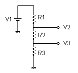

The voltage across each resistor would be equal to its value in kOhms so:

V1 = 11.01333V
V3 = 1.01333V
V2 = 2.4+1.01333 = 3.41333V

Here's where the calculator website comes in. If the above voltages are entered into the three resistor potential divider section, it will generate the nearest combination of standard resistor values which will give us as close to the desired resistor ratio as possible.
http://sim.okawa-denshi.jp/en/teikokeisan.htm

For E24 values it gives:
R1=5.1kΩ
R2=1.6kΩ
R3=680Ω
Which is probably near enough.

E96 values gives:
R1=3.09kΩ
R2=976Ω
R3=412Ω
Which is quite likely more precise than the LM317 so is a bit overkill.

Here's another potential divider tool which only works with two resistors, but can be handy for determining the ratio of R1 and R1: see the results in the "ideal values" section.
https://www.random-science-tools.com/electronics/divider.htm

Exercise for the reader: put the above values back into the original formulas and see how they match to the desired values.
« Last Edit: September 05, 2018, 12:57:53 pm by Hero999 »
 

Online Zero999

  • Super Contributor
  • ***
  • Posts: 19990
  • Country: gb
  • 0999
Re: PWM for LM317 - how to increase resolution?
« Reply #28 on: September 05, 2018, 01:12:20 pm »
Here's a spreadsheet which calculates the values of R1, R2 and R3.
 

Offline joeyjoejoeTopic starter

  • Frequent Contributor
  • **
  • Posts: 274
  • Country: ca
Re: PWM for LM317 - how to increase resolution?
« Reply #29 on: September 05, 2018, 08:46:37 pm »
I might need some guidance on filtering.

I'm not sure what I was doing before, but now I'm getting 200mV ripple. The issue is this is throwing off the ADC in reading the voltage output of the regulator. I'm going to take a look at your earlier post and split up R1 and see if that gets things under control.
 

Online iMo

  • Super Contributor
  • ***
  • Posts: 5243
  • Country: bj
Re: PWM for LM317 - how to increase resolution?
« Reply #30 on: September 05, 2018, 09:35:05 pm »
I think you will get large ripple as the resistors and capacitors are rather small values. You would need high PWM freq to get ripple small.
I would go with an opamp ie the LM358 as the buffer (or put the LM317 inside the opamp loop). The PWM filter could be then with large R and C --> small ripple even with low freq PWM..
« Last Edit: September 05, 2018, 09:36:38 pm by imo »
Readers discretion is advised..
 

Offline joeyjoejoeTopic starter

  • Frequent Contributor
  • **
  • Posts: 274
  • Country: ca
Re: PWM for LM317 - how to increase resolution?
« Reply #31 on: September 05, 2018, 09:38:17 pm »
I think you will get large ripple as the resistors and capacitors are rather small values. You would need high PWM freq to get ripple small.
I would go with an opamp ie the LM358 as the buffer (or put the LM317 inside the opamp loop). The PWM filter could be then with large R and C --> small ripple even with low freq PWM..

So I briefly looked at higher PWM freq. I'm using a 32u4, so it has a 16 bit timer which might help. In doing so temporarily bricked it, so I'm working on getting it back now :)

EDIT : Back in business. I got PWM going as well. 10-bit gives me great resolution at 2kHz. 9-bit a bit less at 4kHz.

If I'm doing this right, at 2kHz, I can get a decent filter with 2k and 47u.


I think the time constant would be good enough for a battery charger.

In any case, I think I have some work to do with filter both the output as well as potentially my bench supply. Time for more reading!
« Last Edit: September 06, 2018, 01:24:19 am by joeyjoejoe »
 

Online Zero999

  • Super Contributor
  • ***
  • Posts: 19990
  • Country: gb
  • 0999
Re: PWM for LM317 - how to increase resolution?
« Reply #32 on: September 06, 2018, 07:59:54 pm »
I think you will get large ripple as the resistors and capacitors are rather small values. You would need high PWM freq to get ripple small.
I would go with an opamp ie the LM358 as the buffer (or put the LM317 inside the opamp loop). The PWM filter could be then with large R and C --> small ripple even with low freq PWM..

So I briefly looked at higher PWM freq. I'm using a 32u4, so it has a 16 bit timer which might help. In doing so temporarily bricked it, so I'm working on getting it back now :)

EDIT : Back in business. I got PWM going as well. 10-bit gives me great resolution at 2kHz. 9-bit a bit less at 4kHz.

If I'm doing this right, at 2kHz, I can get a decent filter with 2k and 47u.

I think the time constant would be good enough for a battery charger.

In any case, I think I have some work to do with filter both the output as well as potentially my bench supply. Time for more reading!
Where are you thinking of putting the 2k resistor?

Any resistance in series with the PWM input will change the potential divider scaling factor.

Don't forget that the output impedance of a potential divider is equal to the value of the two resistors in parallel, so R in your RC circuit should be the values of R1 and R2 in parallel. For example, if R1 = 5k6 and R2 = 2k4, then R for the purpose of your RC circuit is:

R = (R1*R2)/(R1+R2) = (5.6k*2.4k)/(5.6k+2.4k) = 1.68k.

If the capacitor value is 100μF, then the RC constant is:
τ = RC = 1680*100×10-6 = 168×10-3 = 168ms


Offline joeyjoejoeTopic starter

  • Frequent Contributor
  • **
  • Posts: 274
  • Country: ca
Re: PWM for LM317 - how to increase resolution?
« Reply #33 on: September 06, 2018, 08:26:23 pm »
I was thinking of doing an RC filter on the final output stage of the regulator. I'm now second guessing this...
 

Online Zero999

  • Super Contributor
  • ***
  • Posts: 19990
  • Country: gb
  • 0999
Re: PWM for LM317 - how to increase resolution?
« Reply #34 on: September 07, 2018, 07:38:18 am »
I was thinking of doing an RC filter on the final output stage of the regulator. I'm now second guessing this...
On the output? No that's a bad idea. It will increase the output impedance of the regulator, which will severely restrict the output current.
 

Offline joeyjoejoeTopic starter

  • Frequent Contributor
  • **
  • Posts: 274
  • Country: ca
Re: PWM for LM317 - how to increase resolution?
« Reply #35 on: September 07, 2018, 04:43:32 pm »
Okay. I should have done this sooner, a picture is worth a thousand words :) Here's what I'm trying to smooth out. Note PWM freq is 2kHz.

Yellow is the pure PWM output.

Blue is between R1 and R2.

Purple is the output of the LM317.


Offline mikerj

  • Super Contributor
  • ***
  • Posts: 3336
  • Country: gb
Re: PWM for LM317 - how to increase resolution?
« Reply #36 on: September 07, 2018, 05:32:52 pm »
This is one of those cases where you'd be far better off filtering the PWM and then buffering it, since you need to drive into a low impedance.  This also means you can use a multi-pole filter to provide low ripple without making the response very sluggish.

Another point here is that the LM317T has a minimum load current to meet the datasheet regulation performance.  Normally this is achieved by making R3 a low value, 120 or 240 ohms is common (120 ohms is needed to meet worst case 10mA spec.).  With 1k2 as shown in the diagrams here, the minimum load will not be met if nothing else is connected to the regulator output.

That said the scope shows some very sharp edges on the output ripple.  If you were seeing residual ripple on the adjust pin then you would expect to see a sawtooth waveform here, so it's quite likely you are seeing some of the PWM signal being superimposed on the output.  This will happen if you don't have a really good, low impedance ground connection to connect the regulator circuit back to the PWM source.
 

Offline joeyjoejoeTopic starter

  • Frequent Contributor
  • **
  • Posts: 274
  • Country: ca
Re: PWM for LM317 - how to increase resolution?
« Reply #37 on: September 07, 2018, 05:53:47 pm »
I do have a 410ohm resistor as a dummy load going to ground.

I originally had a buffer, but I believe Hero thought it would work better without, or that maybe I would need a different op-amp then the 358.
 

Online Zero999

  • Super Contributor
  • ***
  • Posts: 19990
  • Country: gb
  • 0999
Re: PWM for LM317 - how to increase resolution?
« Reply #38 on: September 07, 2018, 09:03:24 pm »
I don't see who this ripple is a problem for a battery charger. If you connect a battery to the output, you'll find it will be attenuated hugely.

Yes, a buffer is unnecessary, if the circuit can be designed with the impedance of the potential divider in mind. The problem with adding a buffer is it needs to be able to pull the LM317 all the way down to 0V, which the LM358 can't do. An alternative is to use an op-amp which can sink a reasonable amount of current, such as the MCP6021.

What values are you using for R1, R2 and R3 now?

It's possible to put another RC circuit before the potential divider, but its impedance needs to be taken into account. For example, in first circuit I posted R1 = 5k6, R2 = 2k4 and R3 = 1k2, R1 can be split into two resistors, of 2k and 3k6, which total 5k6 and a capacitor added to 0V. The scaling factor of the potential divider is not altered, but the output will be smoother, since it has another stage of filtering.


Offline joeyjoejoeTopic starter

  • Frequent Contributor
  • **
  • Posts: 274
  • Country: ca
Re: PWM for LM317 - how to increase resolution?
« Reply #39 on: September 08, 2018, 01:35:48 am »


Okay, things are looking aweeeesome!

Blue is ADJUST. Magenta is the output voltage. :) I wanted to make sure I cleaned up what I could without any major load, as I spent a few hours tinkering with code to realize it was likely the ADC picking up noise. Now I can rule that out.

At 0% PWM, I'm seeing ~3.55v, and 100%, ~4.7V :)

I think the noise floor of my desk is 200mV though. So I won't get too hung up on that for now :) Plus a bread board won't help. I can run V1 of a PCB with some test points to see how much tighter I can get things.
 

Online Zero999

  • Super Contributor
  • ***
  • Posts: 19990
  • Country: gb
  • 0999
Re: PWM for LM317 - how to increase resolution?
« Reply #40 on: September 08, 2018, 01:56:32 pm »
Good, I'm glad you got the two stage RC filtering working.

An alternative is to put the additional RC circuit after the potential divider and adjust the other resistor in the LM317 circuit to compensate. It does make the calculations more difficult and isn't any better, but I thought I'd show it for completeness.

 
The following users thanked this post: joeyjoejoe

Offline StillTrying

  • Super Contributor
  • ***
  • Posts: 2850
  • Country: se
  • Country: Broken Britain
Re: PWM for LM317 - how to increase resolution?
« Reply #41 on: September 08, 2018, 02:07:11 pm »
You could switch CH2 and CH3 to AC coupling and increase the sensitivity to get a better look at the ripple.

I get the p-p ripple to be under 5mVpp with just the one 100uF filter.  :-//
.  That took much longer than I thought it would.
 

Online iMo

  • Super Contributor
  • ***
  • Posts: 5243
  • Country: bj
Re: PWM for LM317 - how to increase resolution?
« Reply #42 on: September 08, 2018, 04:52:57 pm »
May be a bit off topic, but I could not resist to try with an LM358 + LM317:
With 500us PWM period:
Code: [Select]
Duty    Vout
---------------------------
 50us   1.5023V
100us   3.0001V
150us   4.5002V
250us   7.497V
400us  11.996V
499us  14.964V
« Last Edit: September 08, 2018, 04:55:40 pm by imo »
Readers discretion is advised..
 

Online Zero999

  • Super Contributor
  • ***
  • Posts: 19990
  • Country: gb
  • 0999
Re: PWM for LM317 - how to increase resolution?
« Reply #43 on: September 08, 2018, 11:13:12 pm »
May be a bit off topic, but I could not resist to try with an LM358 + LM317:
With 500us PWM period:
Code: [Select]
Duty    Vout
---------------------------
 50us   1.5023V
100us   3.0001V
150us   4.5002V
250us   7.497V
400us  11.996V
499us  14.964V
That's a perfectly good circuit, but yes it is a little off topic. It has gain, whilst the original poster wanted some loss, i.e. a narrower range of output, than input voltages. A transfer function of VOUT = VIN/4.166+3.5.

It is doable with an op-amp and even a transistor, rather than the LM317, if the short circuit and thermal protection aren't needed.

Here's an alternative solution.

I used the formulae on this site to help to design the circuit.
http://earmark.net/gesr/opamp/gain_offset.htm

Here's the section applicable:
http://earmark.net/gesr/opamp/case7.htm

Unfortunately the calculator isn't very good at picking out the optimum values or just giving the ratio, as the value for R1 has to be selected manually, so I copied the formula into a spreadsheet and used the solve function to generate the exact ratio of R1, R2 and R3, yes I could have spent ages revising how to do this the old way, but I'm lazy. I then put the ratio into the potential divider calculator, linked to earlier, which gave the optimum E24 values.

The plain old LM358 can be used for the op-amp. If more than a couple of hundred mA is required, then both channels of the op-amp can be connected in parallel to give more base drive to Q1. For even higher currents, Q1 will need to be a Darlington or Sziklai pair.
« Last Edit: September 08, 2018, 11:17:56 pm by Hero999 »


Share me

Digg  Facebook  SlashDot  Delicious  Technorati  Twitter  Google  Yahoo
Smf