I am not saying the FTDI chip is the cause btw. Just that when removed and replaced with a known working one, there is no boot loader issues.
I am pretty much on board with the issue being the board design. Probably just coincidence that the old FTDI is working and the new ones are not?
Only tested a handful.
Possible fake FTDI chips? Hack a bad board to loop the FDTI's RX and TX pins, open the USB serial port with a terminal program and see if it responds NON GENUINE DEVICE FOUND!character by character as you type instead of the loopback echoing what you type. (see: https://www.eevblog.com/forum/microcontrollers/ftdi-gate-2-0/ )
I don't think so. They all have different serial numbers. They were cheap though at $2.78 per chip.
Doing as you said, it just echos back what I type.
If you think the FTDI chip might be involved, the next step is to work out possible ways in which it could cause the symptoms you're seeing.
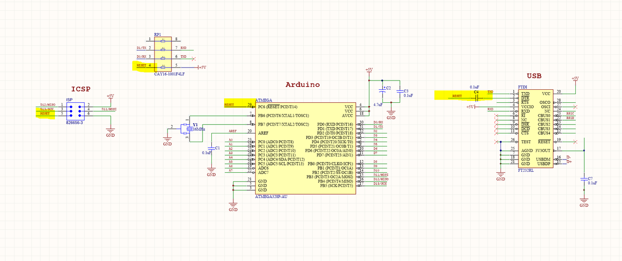
Are there any physical pins on the FTDI chip that are also shared with pins which are needed to burn your boot loader?
Without knowing the details of your design, I'd suggest two possibilities - either:
a) there's a logic signal (or signals) in common. Are your programming (SPI / reset) pins connected to the FTDI, or are they separate? If they're completely separate, then it really shouldn't be able to interfere with boot loading via that route.
b) they share a common power supply, and something bad is happening which is causing the voltage at the MCU to go out of spec during programming. Does anything get warm?
Another option (c) is that the FTDI chip is a complete red herring, and the difference is caused by heating, cooling and flux contamination of your PCB when you remove and replace components. Be sure to thoroughly clean the board after every rework operation, especially in and around the MCU crystal if it has one.
No shared pins for boot loading other than RESET.
Boards are pretty clean. Been using acetone as that is all I have :/
Be careful to not conflate problems... looks like the earlier revision boards have a reliability issue but that needs proper post-mortem analysis.
Rev3 boards...
And once the PCBs arrived, none of them would allow me to burn the boot loader onto the ATMEGA via the programming header.
This is a probably a different problem, consider your design/manufacturing to be flawed and work from first principles on one board. Does your PCB software have a rules check? Check the uP pins for things that are GND that shouldn't be.
Populate one board with the bare minimum to program the uP onboard and work backwards.
Good Luck!
I tried with just the ATMega328p, crystal and cap on the reset pin.
Pretty sure it burned the boot loader. Was a few days ago and forgot to write it down. Ill try again.
Have you gotten boards back from customer? i.e. customer returns.
If you get a customer return board back on your bench does it work?
I second that question, and don't think the OP has answered it (unless I overlooked some comment). This is an important step in finding the root cause of the failures in the field.
@Jackster: Do you actually know that the boards somehow "broke" in transit? Or are they still in the same shape they were in when you sent them out, but don't work at the customers while they still work when you (re-)test them at home?
The boards are sent out in an aluminium case.
They are physically fine. They just develop a fault where the software no longer cycles.
This can happen on new boards too. It will go through the code 3-6 times and then hang.


