Author Topic: noise and jitter on PWM of sine wave inverter, is that normal?  (Read 1318 times)

0 Members and 1 Guest are viewing this topic.

Offline JeanFTopic starter

  • Regular Contributor
  • *
  • Posts: 143
  • Country: fr
Hello,

I purchased a second hand “pure sine” inverter. It was cheap (15 €) and the seller said it was “like new” so I assumed it would be functional. Its robust look and the “made in Switzerland” statement piqued my interest.

link to the actual product

In fact, it didn’t work at all, but fortunately fault-finding was easy. It seems to have encountered an overvoltage situation, and a 15 V Zener and its series resistor that were across the 12 V input were destroyed. Temporarily replacing the resistor with a jumper and removing the Zener showed that the rest of the circuit was still OK.

The inverter seems to work, and I’ve been able to power a corded Dremel with it (that was the main goal of this purchase, as I’ve a little bit of grinding to do in a remote area and I wasn’t sure I wanted to buy a cordless Dremel just for that).

But the inverter emits a rather unpleasant buzzing noise. Not super loud, but definitely noticeable. The unit claims to be “for stand-alone applications”, and I’m not sure a customer who just paid 250 € / 300 CHF for a brand new unit would be happy to hear it 24/7 in his RV or boat. Maybe the noise is perfectly normal; I just don’t have any way to compare with a new unit!

The noise doesn’t change with load. But what I find a bit strange is that this is not only a constant hum, there is also a “KRRCHHRRRKKK… KRRRCHH….. KCHCHRRRCHCRRKK” noise on top of it, which appears to be random.

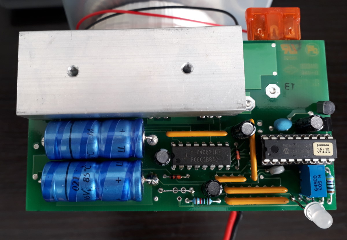
Here is a picture of the board :


As a learning exercise I made a schematic: PDF version


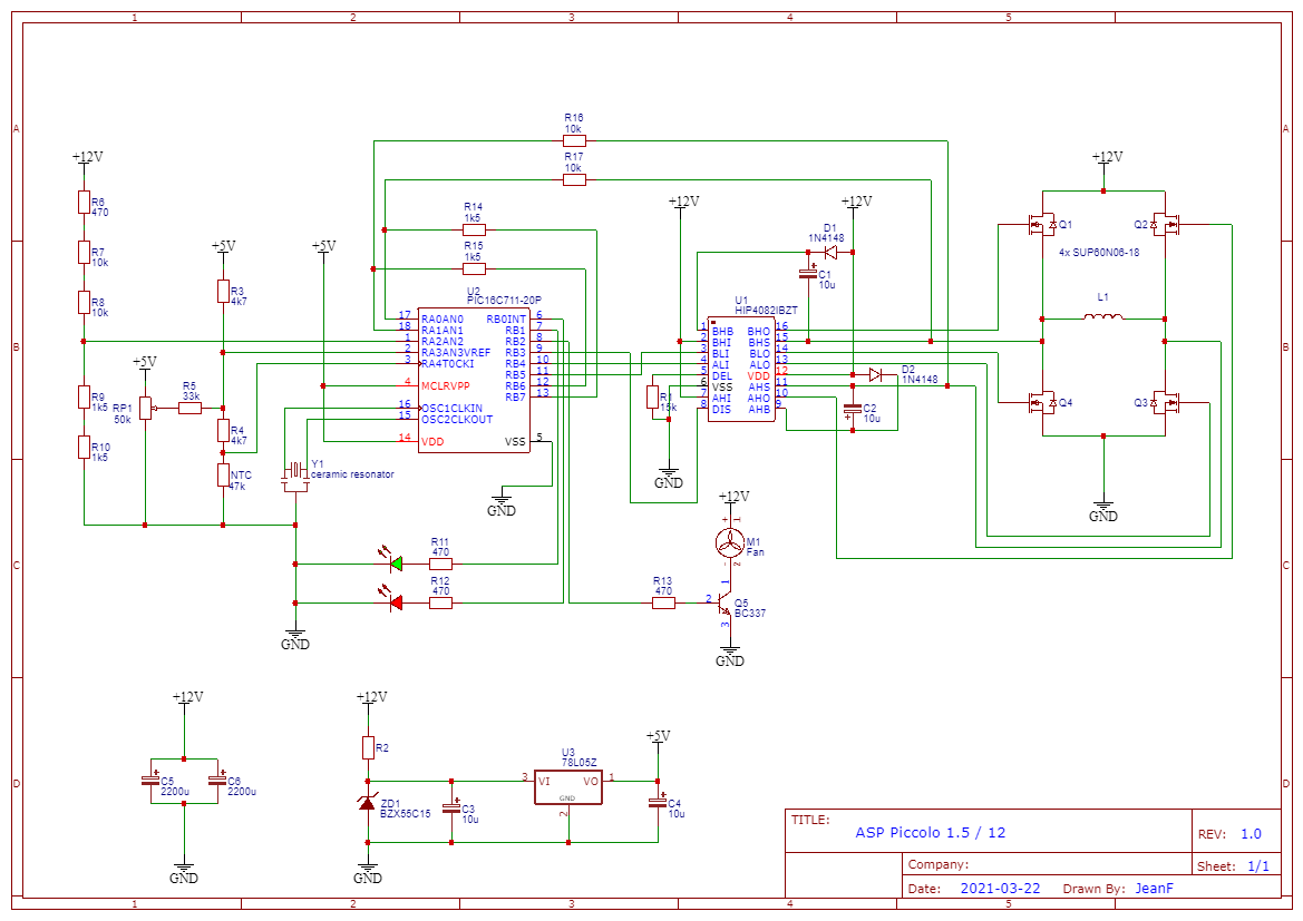
On the secondary side of the transformer there is only a 0.47uF MKT capacitor across the winding + two 0.01uF ones to chassis ground, nothing more.

It’s the first time I study an inverter but I think the waveforms I saw when probing around made sense.

However I noticed there is a bit of jitter on the PWM signals sent by pins 10/11 of the PIC to the pins 3/4 of the FET driver, as seen here :


That happens at the beginning of each new half cycle of the sine wave, in both polarities.

Do you think it’s normal? As the PIC is probably going through a lookup table to determine the pulse length, I can’t imagine anything introducing randomness there, but I may be wrong of course. May the PIC be making adjustments to compensate for a division problem between its own clock and the wanted 50 Hz output?

The PIC also monitors the input voltage and also there is an overcurrent protection (I guess it does so by monitoring the voltage on the primary), maybe there are timing issues with the code that takes care of that…

May this be related to the ceramic resonator? It’s marked “ 160U. “ but I’ve not been able to probe it, with a scope or even with the 10M input impedance of my DMM, it stops oscillating when I probe on PIC pin 15.

If you have any info on this, I’d be glad to hear.
Thanks!


Offline janoc

  • Super Contributor
  • ***
  • Posts: 3811
  • Country: de
Re: noise and jitter on PWM of sine wave inverter, is that normal?
« Reply #1 on: March 24, 2021, 12:44:46 pm »
Jitter in the pwm is likely normal, that's the feedback loop doing its job. If it was not "jumping around" the setpoint, there would be no error signal to steer the controller anymore and the regulation would fall apart.

The resonator would play only a small role because while it drifts over time it is certainly not this fast.

However, if that's all there is to it in your schematic, then this "inverter" would take the shortest route to the bin. No protections for the FETs? No snubbers? No fuse/protection on the secondary? (which you didn't draw but there doesn't seem to be much visible in your photo neither, only that orange automotive fuse for the 12V input).

Oh and that noise you are hearing is likely from the transformer. Could be just making noise because the windings vibrate and you hear the changes in the switching frequency (100us gives about 10kHz, so that is going to be audible). However, it is possible that it is even arcing somewhere due to poor/damaged insulation.

Also the board isn't conformally coated so if someone actually tried to use this on a boat, it would likely have a very short life with the moisture and all.

« Last Edit: March 24, 2021, 12:53:12 pm by janoc »
 

Online T3sl4co1l

  • Super Contributor
  • ***
  • Posts: 21906
  • Country: us
  • Expert, Analog Electronics, PCB Layout, EMC
    • Seven Transistor Labs
Re: noise and jitter on PWM of sine wave inverter, is that normal?
« Reply #2 on: March 24, 2021, 04:00:14 pm »
Shrug, could be more like PDM than PWM.  Or maybe hybrid like adjusting frequency when pulse width is minimum.  (That is, if the compare register is 1, PWM can be further reduced by increasing the max count/TOP register.)

Doesn't necessarily have no protection -- who knows what those ADC pins are looking at.  Seems unlikely that it would be able to offer peak current limiting or protection.  I would suspect it's just to watch for gross overload.

That's going into a toroidal transformer?  Those saturate quite sharply, could be you're hearing a flux imbalance and the control is just too crude to better control DC offset.

Tim
Seven Transistor Labs, LLC
Electronic design, from concept to prototype.
Bringing a project to life?  Send me a message!
 

Online langwadt

  • Super Contributor
  • ***
  • Posts: 4512
  • Country: dk
Re: noise and jitter on PWM of sine wave inverter, is that normal?
« Reply #3 on: March 24, 2021, 04:27:46 pm »
Shrug, could be more like PDM than PWM.  Or maybe hybrid like adjusting frequency when pulse width is minimum.  (That is, if the compare register is 1, PWM can be further reduced by increasing the max count/TOP register.)

Doesn't necessarily have no protection -- who knows what those ADC pins are looking at.  Seems unlikely that it would be able to offer peak current limiting or protection.  I would suspect it's just to watch for gross overload.

That's going into a toroidal transformer?  Those saturate quite sharply, could be you're hearing a flux imbalance and the control is just too crude to better control DC offset.

Tim


With the ADCs it could, at least in theory, use Vds/Rdson to measure current


The following users thanked this post: T3sl4co1l

Offline JeanFTopic starter

  • Regular Contributor
  • *
  • Posts: 143
  • Country: fr
Re: noise and jitter on PWM of sine wave inverter, is that normal?
« Reply #4 on: March 24, 2021, 06:54:09 pm »
Thanks everyone,

Yes, the schematic is all there is to it, except I didn’t properly draw the transformer and the triple capacitor (on page 19) that is across the 230V winding and the chassis ground.

Here is the manual that I found. Amusingly, they say
Quote
a high degree built-in safety, excellent dynamic response, a surge-proof and overload-proof output, it is very simple to operate a broad range of applications. The „heart“ of the inverter is a very powerful RISC-microprocessor of the latest generation [hehehehehe, PIC16C711 !] . This microprocessor is responsible for the real time computing of the output sinewave shape, for the process control of the output voltage, for the supervision of the battery (dynamic) and the inverter temperature. The power stage features modern Power Mosfet transistors. These transistors are the key to the high partial-load efficiency and superb overload capability. The power transistors are protected by independent intelligent protection circuits. The inverter is further more protected against DC-overvoltage (static) and short circuit on AC-output.

But some other parts of the manual seem copypasted from a bigger model in the range so who knows.

Here is another picture :


haha, yes, a piccolo it is. Fortunately, not a trumpet nor a bombard…

I’d heard about inverters using lookup tables to output sine values, but naively I was thinking the sine table would be it all, I didn’t know that they could regulate the output voltage by applying a correction factor to the table value for the duty cycle as well.

Well, I’m glad I got it cheaply, I think for my modest requirements it will do the job nicely (although musically)
 

Offline rstofer

  • Super Contributor
  • ***
  • Posts: 9905
  • Country: us
Re: noise and jitter on PWM of sine wave inverter, is that normal?
« Reply #5 on: March 24, 2021, 07:29:51 pm »
There might be some learning to this device if you put the sine wave output on the 2d channel of the scope.

https://electronics.stackexchange.com/questions/191742/how-is-a-pwm-signal-converted-to-sine-using-a-transformer

You might want to trigger on the rising edge of the sine wave where it passes through 0V.  Move the trigger point far to the left and take a single shot.


Share me

Digg  Facebook  SlashDot  Delicious  Technorati  Twitter  Google  Yahoo
Smf