Guys, many thanks for your help.
Let me explain better...
This is a portable air conditioner using
and
as the basic design (the second link should be the same design of the first link with some additional enhancements).
Use the board to trigger a relay
Use the relay to switch the fan
rather defeats having a variable speed fan controller
Yes, themadhippy is right. My goal is to auto regulate the fan speed based on temperature detected from the attached probe. The higher the temperature, the faster the fan speed, while the lower the temperature, the slower the fan speed.
When desired temperature is reached, then the fan will continue to run at minimum speed ("conservation mode").
This is what does the governor and the regular air conditioners.
Benefits are extended fan life, lower power consumption, lower noise.
Same for the water pump. It is not mandatory, but I thought that reducing power supply while in "conservation mode" is a good thing (and even with no control, it is still convenient to connect it directly to the board rather than using other external connections).
Main problem is that most of the similar controllers I found are designed to work with PWM signals which are only available in 3-4 wire fans. My fan is 2 wires (red and black) and therefore I need a controller like this which basically achieve the same result by increasing-decreasing power supply programmatically.
There are voltage to PWM converters like
this, but I feel I'm going to add unneeded complexity and increase chances of issues. Even with this workaround, I think I sill have to go through current limitation. For example on
this PWN controller is stated the following:
Working current: <0.1A
Fan current: <5A (on-board connector can withstand, if you need to control higher power, just walk the power cord separately)
What they mean for
"if you need to control higher power, just walk the power cord separately". it seems an easy workaround that I could apply even to the board I want to buy.
How about get the SFIB2-270-02 version of the fan which runs at 24V, max draw 3A?
Then use a 12 to 24V DC-DC converter to get the 24V.
I would first make sure the fan is compatible with the "linear voltage regulation technology" used by the controller.
Unfortunately too late. I already have the 12V fan in my hands. I spent hours trying to figure out if was better 12V or 24V and I saw that integration with other devices would have become more complex with 24V. In addition to that, all the DIY projects I saw on youtube only use 12V. So, I preferred to stay on the safe side.
Oversize the relay, don't get a 6A relay to switch a 6A fan, use like a 20A relay.
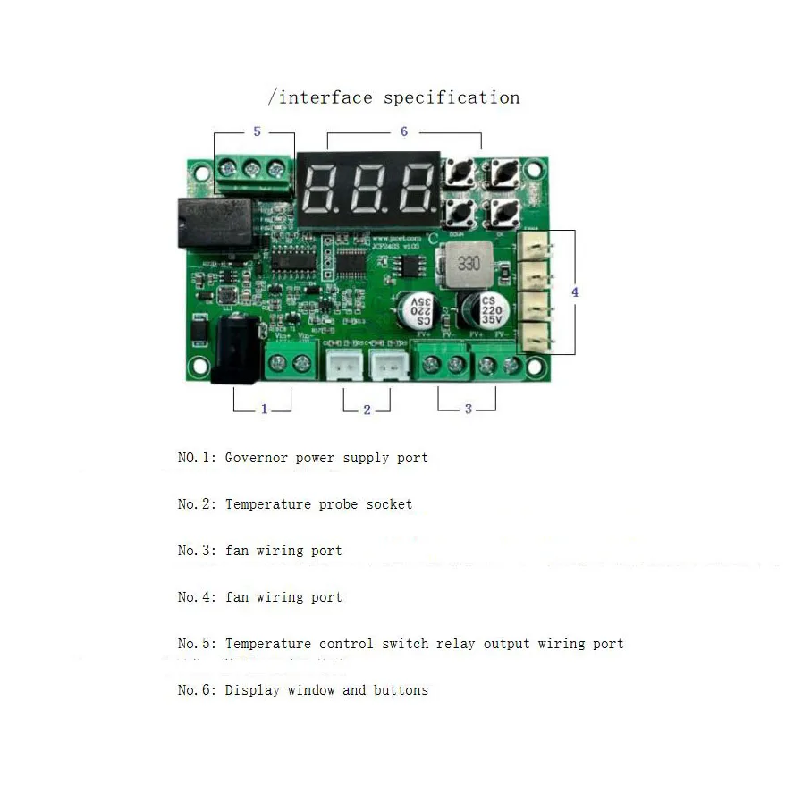
The fans connect to port 4, I suppose there is no current limitation here. I suspect port 3 is to connect fans in "power off mode" (no speed regulation):

From google I read this:
How can I increase amperage without increasing voltage?If the electrical circuit contains IC chips called resistors, resistance can also be lowered by using a lower rated resistor, for example, changing a 4 ohm resistor to a 2 ohm resistor. In a circuit, cutting the resistance by half and leaving the voltage unchanged will double the amperage across the circuit.This seems to be a very risky operation. Board is designed for 3A and who know how many bad things could happen with such modification.
Any idea, guys?
I really need to complete my air conditioner project as soon as possible: from the place I'm writing this thread, temperature reached 35 C° and is worse than hell !
Thanks