Author Topic: HAKKO FX-888 Switch Mod  (Read 8162 times)

0 Members and 1 Guest are viewing this topic.

Offline DROBNJAKTopic starter

  • Contributor
  • Posts: 31
HAKKO FX-888 Switch Mod
« on: December 10, 2012, 05:24:40 pm »
Watching too many Dave's videos got me into a trouble and I got myself a HAKKO FX-888 soldering iron. Now, I watched front LED mod video, as well, but hopefully found easier way.

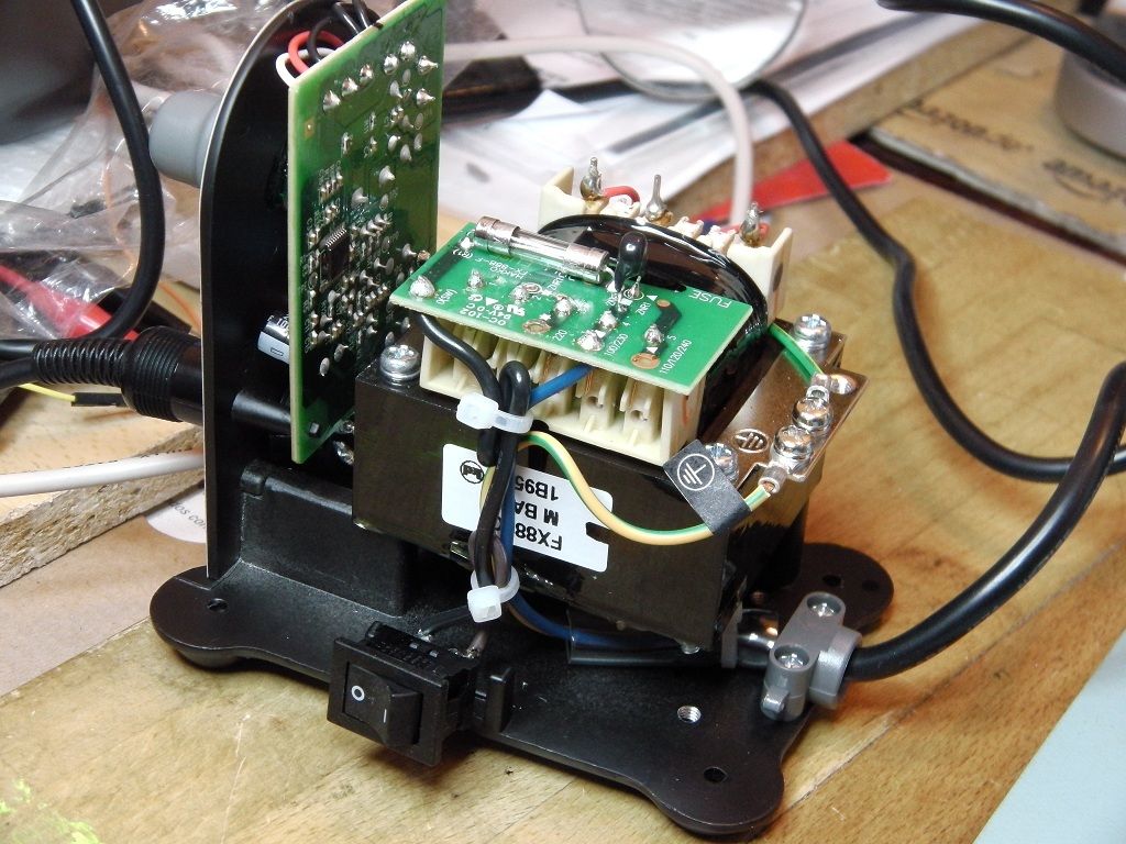
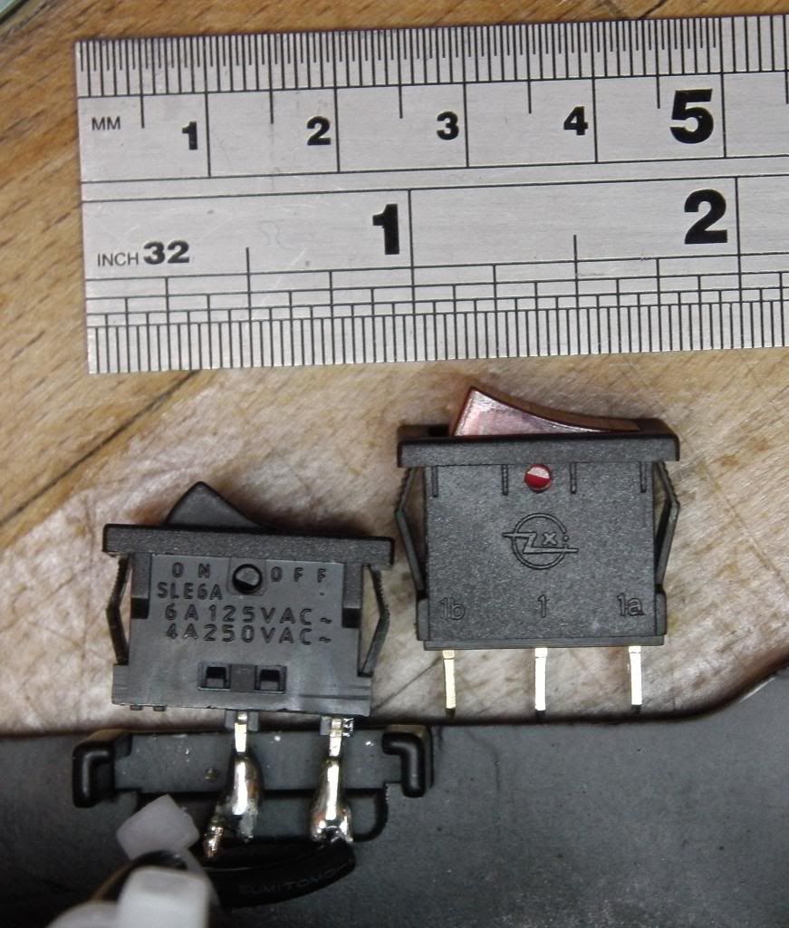
There are these illuminated rocker/toggle AC switches out there on eBay. But, my problem is I am not 100% sure how to replace the original switch. As you can see from pics, the original switch has two pins connected to two wires, while illuminated switch has three terminals. Now, that means, I need one extra wire?

Am I right in guessing that I should connect Black and Dark-Pink wires to silvered terminals (1 and 1a in the photo) of the illuminated switch and leave the brass-colored (1b in the photo), supposedly Ground terminal, unconnected?

Or, should I connect terminal (1a) to Black wire, terminal (1) to Dark-Pink and than pull Yellow-Green wire, from the steel plate, to terminal (1b)?

By the way, this is UK version, with UK plug and lead.


« Last Edit: December 10, 2012, 05:27:02 pm by DROBNJAK »
 

Online IanB

  • Super Contributor
  • ***
  • Posts: 12398
  • Country: us
Re: HAKKO FX-888 Switch Mod
« Reply #1 on: December 10, 2012, 05:33:03 pm »
Those illuminated rocker switches should come with a wiring diagram showing how to connect the terminals. From memory, one terminal connects to the live supply, one terminal connects to the load, and the third terminal connects back to the neutral of the mains supply. But don't experiment or bad things will happen. Follow the wiring diagram that should have come in the instructions with the switch.
 

Offline DROBNJAKTopic starter

  • Contributor
  • Posts: 31
Re: HAKKO FX-888 Switch Mod
« Reply #2 on: December 10, 2012, 06:00:48 pm »
... From memory, one terminal connects to the live supply, one terminal connects to the load, and the third terminal connects back to the neutral of the mains supply. ...

yeah, that would be a standard way to wire a switch, but HAKKO is not using ground.

Any other opinions?
 

Offline SLJ

  • Frequent Contributor
  • **
  • Posts: 657
  • Country: us
  • Antique Test Equipment Collector
    • Steve's Antique Technology
Re: HAKKO FX-888 Switch Mod
« Reply #3 on: December 10, 2012, 06:13:43 pm »
There is a ground there though and a neutral coming in you can use.  Just because it's not on the original switch does not mean you can't use it to power the lighted switch.  You need to look at the paperwork to see which connectors on the switch are which.  You could also use an ohm meter to figure it out.

Online IanB

  • Super Contributor
  • ***
  • Posts: 12398
  • Country: us
Re: HAKKO FX-888 Switch Mod
« Reply #4 on: December 10, 2012, 06:14:23 pm »
There is no "ground" on the switch. I didn't mention ground in my reply.

You are in the UK. "Dark pink" is brown, and is the mains live conductor from the supply cable. Blue is the neutral supply conductor. Green/yellow is the protective earth conductor.

The earth conductor should not be connected to anything other than what it is already connected to.

As I mentioned above, don't guess about this stuff--follow the wiring diagram that comes with the switch. If you don't have a wiring diagram, don't experiment.

I get the impression you don't really know what you are doing. Therefore I strongly advise you not to modify the soldering station. Just leave it be and trust that it works.
 

Offline SeanB

  • Super Contributor
  • ***
  • Posts: 16366
  • Country: za
Re: HAKKO FX-888 Switch Mod
« Reply #5 on: December 10, 2012, 06:40:10 pm »
Multimeter set to continuity, and check between the centre and the outer pins in turn, then operate the switch. Whichever has continuity to the centre is the live input, the centre is the output and the other is connected via a 100k 0.5W resistor to the neutral conductor.  The light is a neon with an integral resistor, connected to the centre pin and one of the outer ones. Thus the other is the mains input.

I recently converted one of these to replace the neon with a 3mm red LED, as i had the switch but wanted a 12V illuminated version. A little bit of work and it works well, with the led wires replacing the neon and resistor in the switch body.
 

Online IanB

  • Super Contributor
  • ***
  • Posts: 12398
  • Country: us
Re: HAKKO FX-888 Switch Mod
« Reply #6 on: December 10, 2012, 07:22:07 pm »
Whichever has continuity to the centre is the live input, the centre is the output and the other is connected via a 100k 0.5W resistor to the neutral conductor.

From the pictures and the switch labelling, it seems like the centre is the live input and one of the outer pins goes to the load? The photo of the original switch seems to show the brown wire connected to the centre contact. Could it be that different switches have different pin-outs?

Quote
The light is a neon with an integral resistor, connected to the centre pin and one of the outer ones. Thus the other is the mains input.

If the neon has an integral resistor, why also include an external 100k 0.5W resistor?
 

Offline Bored@Work

  • Super Contributor
  • ***
  • Posts: 3932
  • Country: 00
Re: HAKKO FX-888 Switch Mod
« Reply #7 on: December 10, 2012, 07:42:25 pm »

From the pictures and the switch labelling,

That labelling is strange, because it (1, 1a, 1b) would indicate a SPDT switch. An  illuminating switch should have 1, 1a and 2. Where a SPST switch is between 1 and 1a, and the lamp between 1 and 2.
I delete PMs unread. If you have something to say, say it in public.
For all else: Profile->[Modify Profile]Buddies/Ignore List->Edit Ignore List
 

Offline SeanB

  • Super Contributor
  • ***
  • Posts: 16366
  • Country: za
Re: HAKKO FX-888 Switch Mod
« Reply #8 on: December 10, 2012, 07:51:05 pm »
Resistor is both in case you made a mess up, and to prolong the little neon lamp life. Having 150V across a 1/8W resistor with a voltage rating of 100V is not exactly a good thing. The extra resistor keeps it safe if the little resistor arcs over when it gets hot or gets damp.
 

Offline DROBNJAKTopic starter

  • Contributor
  • Posts: 31
Re: HAKKO FX-888 Switch Mod
« Reply #9 on: December 11, 2012, 09:35:33 am »
The second photo doesn't offer all the necessary clues, because of the angle. After reading all your comments, I had a second look. The Brown wire comes straight from the mains cable, into the middle pin of the existing switch. That is Live. The Black existing switch wire, is connected to the Load or to the HAKKO itself. That setup seems logical, because it would be nasty if both Brown and Black wires were coming directly from the cable  :-+

I tried continuity as well. HAKKO's original switch only has continuity when when on "I", which is another logical thing. And my illuminated switch has continuity only when on "I". So I would say that is three logical premises confirmed, so we should be good to go. I am going to plug illuminated switch in and report back.
 

Offline DROBNJAKTopic starter

  • Contributor
  • Posts: 31
Re: HAKKO FX-888 Switch Mod
« Reply #10 on: December 11, 2012, 03:09:00 pm »
Here it is, I've just tested it:

Illuminated Switch              --> Hakko FX-88
Terminal:

Non-Silvered, Copper (1b)  --> Neutral (Blue, UK) wire
Middle, Silvered, (1)            --> Load (Black on HAKKO FX-88) wire
Silvered (1a)                       --> Live (Brown, UK) wire

Note: I am using UK standard plug.

There is this switch wiring diagram: http://www.electro-tech-online.com/custompdfs/2009/04/51418.pdf

My Illuminated Toggle AC Switch has these specs:

type ... SPDT
Max current ... 6A @ 250 VAC
Max current ... 10A @ 125 VAC

Please use caution when connecting and double-check wiring, because your switch might be different.
« Last Edit: December 11, 2012, 05:20:52 pm by DROBNJAK »
 

Offline SeanB

  • Super Contributor
  • ***
  • Posts: 16366
  • Country: za
Re: HAKKO FX-888 Switch Mod
« Reply #11 on: December 11, 2012, 04:29:31 pm »
Do not use the frame as return for the switch illumination. Use the neutral connection to the transformer, where the blue mains wire is connected.


Share me

Digg  Facebook  SlashDot  Delicious  Technorati  Twitter  Google  Yahoo
Smf