I am thinking of implementing an idea I had for something connected to a vehicle's OBD port. It will be powered by the +12V supply on the OBD port, which is usually a permanent non-switched feed direct from the battery. However, my device will only need to function when the vehicle's engine is running, so it should remain in a standby/sleep state at all other times. So, because there are no explicit means of determining 'on' state on the OBD port (no ignition-switched power feed, for example), I thought I could probably look at the voltage level to determine if the engine is running.
When 'off', the voltage will just be whatever the state of charge the battery is at - e.g. 12.x volts (or less). When 'on' and engine running, the alternator will be charging the battery, so the voltage level should be higher - probably at least 13V. Sounds right?
I think a comparator circuit should so the trick, especially as what I want out of it is a simple logic-level signal to feed to a microcontroller to tell it to either wake up or sleep.
I came up with the following circuit:
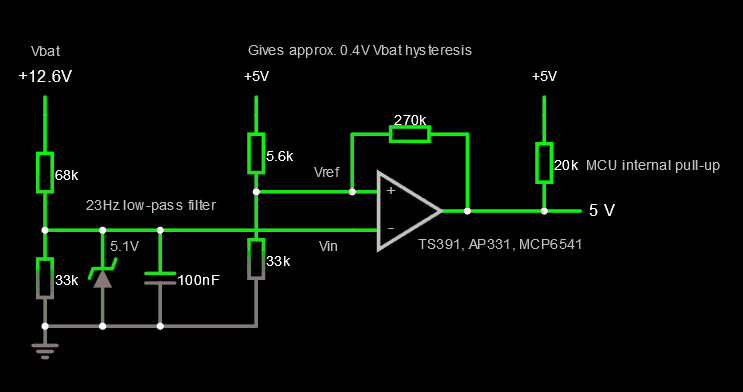
The salient points:
- Inverting arrangement; active-low output signal.
- Vbat gets divided such that approx. 13V is turned into 4.3V, plus low-pass filtered to avoid errant transients.
- A 5.1V zener protects the inverting input of the comparator should Vbat go any higher than expected.
- Vref is fed from +5V VCC, divided to about 4.3V. Feedback gives some hysteresis, of about 0.4V on Vbat.
- Output will use internal pull-up on connected MCU pin to ensure a defined high level when comparator is not triggered.
How does it look? Is there anything I have missed, or any way I could improve it?
Specifically, one query I have is if the input is low-pass filtered (and thus slow to rise/fall), is there any point in implementing any hysteresis? As the output is feeding an interrupt on the MCU, I suppose it is best to ensure no spurious oscillation, but I can't help wondering if I can get away without it.
Another thing I am concerned with is current draw, as this circuit will be always-on. I think it should be low power, as the simulation suggests that no more than a few hundred microamps will be drawn, but the sim gives no scope to measure current drawn by the comparator itself. What will be the current draw of a single-channel comparator?
For choice of comparator, I have been looking for something ubiquitous and cheap in a SOT package - the noted part nos. (TS391, AP331, MCP6541) are ones I've found so far. Will they be suitable?
By the way, I should probably mention that while my chosen MCU (AVR) actually features a built-in analog comparator peripheral, I cannot use it because disappointingly it does not appear to support waking up from standby/sleep modes upon a comparator interrupt, so I'll have to use an external circuit.


