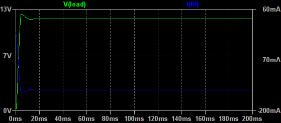
By the way, at 100% PWM that LC filter you provided shows a voltage spike before stabilizing. Is that something I should be concerned about? I'm not sure if ~20ms is long enough for such a spike to be dangerous.
 EDIT 1
: Changing the placement of the diode seems to cut off the spike as it should:

 EDIT 2
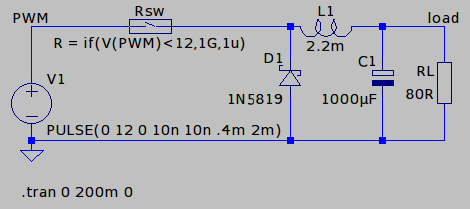
: Because I do not need the smoothing to be perfect I tried an LC filter with a smaller inductor. This actually seems to work quite well. The control curve is much better than an RC filter while also getting closer to 12V. The question remains:
is this a sane thing to do?I'm using a 1N5819 here because I have a few of those lying around. For the inductor values I used a 5900-222-RC (axial, 2.2mH, 1.7RDC, 500mA).

10% PWM: (this would be the lowest setting for practical use)
20% PWM:

30% PWM:

50% PWM:

100% PWM:
 EDIT 3
: This is probably a better way to do the flyback diode:
Having the diode in this configuration does raise the output voltage at low duty cycles: 10% PWM has gone from 3.3V to 5V.
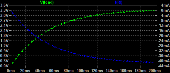
EDIT 4: Added a resistor to the flyback diode to dampen the effect of the inductor during the off-portion of the PWM cycles. Mostly to improve the control curve, so I can have access to low voltages (3-4V) without resorting to ultra-low PWM duty cycles (<=5%).

Control curve now looks like this:
PWM% => Vout
   5 =>  1.3
   6 =>  1.7
   7 =>  2.1
   8 =>  2.6
   9 =>  3.0
  10 =>  3.5
  11 =>  3.9
  12 =>  4.3
  13 =>  4.7
  14 =>  5.1
  15 =>  5.5
  16 =>  5.9
  17 =>  6.2
  18 =>  6.5
  19 =>  6.8
  20 =>  7.0
  25 =>  8.2
  30 =>  9.0
  35 =>  9.6
  40 => 10.0
  50 => 10.6
  60 => 11.0
  80 => 11.3
 100 => 11.8


