http://www.pa4tim.nl/?p=1728This is my version. Checked it agains VNA and bridgemeasurements.
Remember, ESR is frequency dependend and at a minimum at SRF. All measured values only are usefull if you know the ESR specified by the manufacturer at the frequency he specified.
A better rating is D, the dissipation factor. That tells you the ratio between R and Xc. An ESR of 1000 ohm is very good for a 100 pF at 1KHz but 0.01 Ohm lousy for a 10000 uF cap at 1 KHz.
The first one has a D of 0.000628 so 0.062% of the power is dissipated in the ESR
The second one has a D of 0.628 so almost 63% of the power is dissipated in the ESR of the cap.
But that 10000 uF at 100Hz and an ESR of 0.01 ohm has a D of 0.0628 and only 6.3% is dissipated.
But most meters like the peak ect measure at 100 or 200KHz. A 10000 uF cap is probably an inductor at those frequency, besides that Xc is 0.000159 Ohm at 100KHz and if the factory gives the specs for 100 Hz you still know swat about this cap. An other good parameter is loss angle but it must be measured vectorial. Good LCR meters use it ( besides D)
Only thing you know that if its real high, the cap is bad. But a scope meaurement would have told you too. I use it if the instrument is a) so bad it can not be powered up or it is not used for long so I have to reform the caps. After reforming i meaure capacitance and D. ( or if I'm lazy i use my esr meter but most times I use a bridge and measure D, or a vna and measure loss angle)
These things happen to caps:
Loss of capacity,
DC leakage,
High ESR.
In real live the first one is very common in smps
The scond in high voltage circuits (also primary SMPS)
The third is not as common as everybody thinks, most just believe those meters to much and do not understand ESR.
All three can come together or appart.
3 other failures are electrode rupture ( sometimes intermittend) or called an open cap.
Intermittend ESR ( i have found some using my analog ESR meter while bridges and VNAs did not noticed it,
Dielectric absorbtion.( more as normal)
From a repair in a dvd/HD player I replaced 34 bad caps. 2 had high ESR.
Just fixed a selfinduction bridge, 1 high D cap and one with degraded 10 nF instead of 100 uF capacitance but perfect ESR.
So an ESR meter is handy when used wise ( and replacing a cap that was not bad after all will do no harm so everybody is pleased and loves their ESR meter.

)
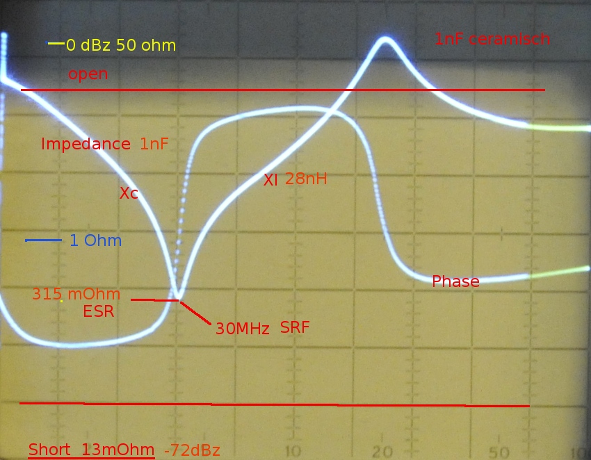
this is what ESR looks like over a frequency sweep using RF-IV measurement on a analog VNA