Author Topic: Detecting a closed circuit with a few complications.  (Read 10256 times)

0 Members and 2 Guests are viewing this topic.

Offline capt bullshot

  • Super Contributor
  • ***
  • Posts: 3033
  • Country: de
    • Mostly useless stuff, but nice to have: wunderkis.de
Re: Detecting a closed circuit with a few complications.
« Reply #25 on: March 02, 2018, 07:03:19 pm »
A simple (and only) solution would be to monitor the current through the "GO" switch. What components to use, depends on the current required by the contactor in normal operation. There are "current sensing" reed relays that may do the job well.
Safety devices hinder evolution
 
The following users thanked this post: system24seven

Offline BrianHG

  • Super Contributor
  • ***
  • Posts: 8156
  • Country: ca
    • LinkedIn
Re: Detecting a closed circuit with a few complications.
« Reply #26 on: March 02, 2018, 07:04:56 pm »
Sorry @drussell, my comment wasn't aimed specifically at you, I'm trying to remind everyone that the OP has no access to the limit switch and contactor relay.

I want my 2 questions answered since that contactor relay may have a 1 amp coil.  Or, it may be an electronic circuit and only draws 25ma from the GO button.  This changes the implementation of my idea and with 1 amp, a resistor solution isn't very reliable or can heat up.

I want to suggest something that will be reliable and guaranteed to work.
« Last Edit: March 02, 2018, 07:07:36 pm by BrianHG »
 
The following users thanked this post: drussell, system24seven

Offline Ian.M

  • Super Contributor
  • ***
  • Posts: 13138
Re: Detecting a closed circuit with a few complications.
« Reply #27 on: March 02, 2018, 07:09:54 pm »
+1.
I asked back in reply#2 for that info:
Detect the current and OR it with the voltage present signal, and you'll have the actual limit switch state.    How you detect the current is highly dependent on how much current there is.   Connect a multimeter on its 10A range in series with the GO button, push it, measure the current and post it here.
However I was having a brain-fart and didn't think of the really simple test of simply connecting the multimeter on Amps directly across the Go button, simulating pushing the button, to measure it.
 

Offline floobydust

  • Super Contributor
  • ***
  • Posts: 7530
  • Country: ca
Re: Detecting a closed circuit with a few complications.
« Reply #28 on: March 02, 2018, 11:45:28 pm »
The wire can be 0V, 24V or floating. There is a way to detect the three possibilities on a single wire, but you need power.
You can use a dual-optocoupler or a couple transistors. This is the sort of idea:
 
The following users thanked this post: system24seven

Offline Ian.M

  • Super Contributor
  • ***
  • Posts: 13138
Re: Detecting a closed circuit with a few complications.
« Reply #29 on: March 03, 2018, 12:11:28 am »
No.  O.P's requirements:
I need to monitor the status of the limit switch.
For physical reasons, I only have access to the "GO Button " half of the circuit.

When the GO Button is not closed, I can detect 24v in parallel to the Go Button if the limit switch is not open.
When the go button is pressed, there is no voltage drop across the go button contacts, so my circuit would report that the limit switch is now open.
What is the easiest way to detect this in both Go Button states?
Your dual opto circuit doesn't indicate the limit switch state while the Go button is pressed.

FAIL  :--
 
The following users thanked this post: system24seven

Offline BrianHG

  • Super Contributor
  • ***
  • Posts: 8156
  • Country: ca
    • LinkedIn
Re: Detecting a closed circuit with a few complications.
« Reply #30 on: March 03, 2018, 01:04:29 am »
Ok, got tired of waiting for the OP to answer this my 2 questions, so, I'll just assume his contactor relay draws a huge current.

My circuit will work from 100ma to 4 amps DC.  At 100ma, the contactor will get 22.8v instead of 24v.  At 4 amps, the contactor will get 22.4v instead of 24v.  I would be surprised if the contactor would fail to properly switch losing approximately 1.5v, or around 6% on it's power supply.  This circuit will handle contactors with 24vdc at up to 90 watts inrush current coils.  For the 24VDC contactors which have a 225 watt inrush current, you will need to go to 10 amp diodes.

Digikey has stock of the diodes and relay.   The relay contacts are only 2 amps.  Larger contact current 1.5v relays exist...

If you need a power relay, use 1 to 2 more diodes in series and an Omron 'G6RL-1A DC3' rated with 10 amp contacts.  Your contactor will now only get 21.6v to 21v.
« Last Edit: March 03, 2018, 02:27:25 am by BrianHG »
 
The following users thanked this post: system24seven

Offline floobydust

  • Super Contributor
  • ***
  • Posts: 7530
  • Country: ca
Re: Detecting a closed circuit with a few complications.
« Reply #31 on: March 03, 2018, 02:21:50 am »
No.  O.P's requirements:
I need to monitor the status of the limit switch.
For physical reasons, I only have access to the "GO Button " half of the circuit.

When the GO Button is not closed, I can detect 24v in parallel to the Go Button if the limit switch is not open.
When the go button is pressed, there is no voltage drop across the go button contacts, so my circuit would report that the limit switch is now open.
What is the easiest way to detect this in both Go Button states?
Your dual opto circuit doesn't indicate the limit switch state while the Go button is pressed.

FAIL  :--

I figured you'd know before and after the GO button is pressed if the limit switch tripped. So we'll have to monitor current to know in real time.

This application sounds like a motor and travel limit switch? Operator presses and holds button and needs to know when you've reached the end?
Most large contactors are AC coil.
 
The following users thanked this post: system24seven

Offline EEVblog

  • Administrator
  • *****
  • Posts: 38798
  • Country: au
    • EEVblog
Re: Detecting a closed circuit with a few complications.
« Reply #32 on: March 03, 2018, 04:07:22 am »
Hi All,

I have been working on solutions to a problem I have in one of my designs.
The basic circuit is the following:

I need to monitor the status of the limit switch.
For physical reasons, I only have access to the "GO Button " half of the circuit.

When the GO Button is not closed, I can detect 24v in parallel to the Go Button if the limit switch is not open.
When the go button is pressed, there is no voltage drop across the go button contacts, so my circuit would report that the limit switch is now open.
What is the easiest way to detect this in both Go Button states?

Assuming there are no grounding issues between you circuit and the switch/relay system, a simple resistor divider should do it. One that reduces 24V to say 3.3V or 5V for whatever logic you are using. Maybe with a reverse diode across the lower resistor for protection.
More complex would be to use an optocoupler.
« Last Edit: March 03, 2018, 04:11:14 am by EEVblog »
 
The following users thanked this post: tpowell1830, system24seven

Offline BrianHG

  • Super Contributor
  • ***
  • Posts: 8156
  • Country: ca
    • LinkedIn
Re: Detecting a closed circuit with a few complications.
« Reply #33 on: March 03, 2018, 05:08:43 am »
Hi All,

I have been working on solutions to a problem I have in one of my designs.
The basic circuit is the following:

I need to monitor the status of the limit switch.
For physical reasons, I only have access to the "GO Button " half of the circuit.

When the GO Button is not closed, I can detect 24v in parallel to the Go Button if the limit switch is not open.
When the go button is pressed, there is no voltage drop across the go button contacts, so my circuit would report that the limit switch is now open.
What is the easiest way to detect this in both Go Button states?

Assuming there are no grounding issues between you circuit and the switch/relay system, a simple resistor divider should do it. One that reduces 24V to say 3.3V or 5V for whatever logic you are using. Maybe with a reverse diode across the lower resistor for protection.
More complex would be to use an optocoupler.

Can you please explain this, or, illustrate you idea.  I'm having trouble visualizing you wiring.
According to many contactor data sheets, for the 24vdc coils units, those coils are specked to consume as much as 3.5amps initially when switched on, then, they settle to 100ma current.  If the OP's circuit is an electronic driven contactor, where there only may be around 10ma in the loop, all I would do is use an optocoupler in the circuit as well.

You can see in my attached data sheet, the 90watts for the 24v DC contactor is 3.75 amps until it is closed when it goes to 2.8 watts, or around 116ma.  This is a huge swing.
« Last Edit: March 03, 2018, 05:11:35 am by BrianHG »
 
The following users thanked this post: system24seven

Offline Brumby

  • Supporter
  • ****
  • Posts: 12393
  • Country: au
Re: Detecting a closed circuit with a few complications.
« Reply #34 on: March 03, 2018, 06:07:42 am »
Before we start getting into solutions, I thought it best to lay out the problem more clearly.  Here is how I understand it...

Two switches having two states each generates four possible states of the system, having the following characteristics:
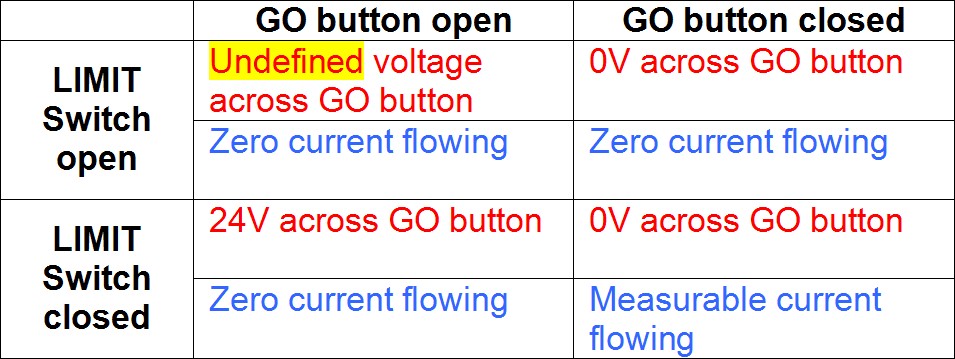


Here we can see three possible measurable quantities for the voltage across the GO button: 0V, 24V and Undefined - and if we have 3 distinct values for this voltage, we can exactly determine the state of the switches when no current is flowing.

However, the undefined value causes a problem.  It could possibly be 0V or 24V, which extinguishes the certainty.

If, however, there could be some unique voltage across the GO button, then the certainty is reinstated.  (I have chosen 12V - but it could be ANY voltage sufficiently different from the nominal 0V and 24V that it can be reliably distinguished from them.)

Inverting the table using observations to determine states produces this:


My solution would introduce a voltage across the GO button from a source of sufficiently high enough impedance that it has no measurable effect on the normal operation of the system, but not so high that the voltage detection mechanism cannot reliably detect it when both switches are open.  There would also be a shunt resistor for detecting current flow.

How these quantities are then processed is open for discussion.
« Last Edit: March 03, 2018, 06:09:40 am by Brumby »
 
The following users thanked this post: system24seven

Offline BrianHG

  • Super Contributor
  • ***
  • Posts: 8156
  • Country: ca
    • LinkedIn
Re: Detecting a closed circuit with a few complications.
« Reply #35 on: March 03, 2018, 06:29:38 am »
Before we start getting into solutions, I thought it best to lay out the problem more clearly.  Here is how I understand it...

Two switches having two states each generates four possible states of the system, having the following characteristics:


Here we can see three possible measurable quantities for the voltage across the GO button: 0V, 24V and Undefined - and if we have 3 distinct values for this voltage, we can exactly determine the state of the switches when no current is flowing.

However, the undefined value causes a problem.  It could possibly be 0V or 24V, which extinguishes the certainty.

If, however, there could be some unique voltage across the GO button, then the certainty is reinstated.  (I have chosen 12V - but it could be ANY voltage sufficiently different from the nominal 0V and 24V that it can be reliably distinguished from them.)

Inverting the table using observations to determine states produces this:


My solution would introduce a voltage across the GO button from a source of sufficiently high enough impedance that it has no measurable effect on the normal operation of the system, but not so high that the voltage detection mechanism cannot reliably detect it when both switches are open.  There would also be a shunt resistor for detecting current flow.

How these quantities are then processed is open for discussion.
Please show me an example schematic of how this could work.  Remember, the OP might have access to an outside voltage source, but, it is not guaranteed.  Also, the op has no access to anything on the right hand side of his schematic, just the 2 wires which go to the GO button.  While the go button is closed, keeping the contactor on, he needs to know if at anytime the limit switch has been opened.

He does not care about the limit switch's position when the GO button is off.  This would be all too easy to detect.
 

Offline Brumby

  • Supporter
  • ****
  • Posts: 12393
  • Country: au
Re: Detecting a closed circuit with a few complications.
« Reply #36 on: March 03, 2018, 06:42:10 am »
I've already thought of two three ways.  Give me some time to draw something up.

Knowing the current draw and tolerance of the existing system to a voltage drop across a shunt resistor would be nice - but I'll just throw in some numbers to make it work.

He does not care about the limit switch's position when the GO button is off.  This would be all too easy to detect.
Don't do this.  As a first pass, ignoring one of the valid states BEFORE you have a solution is a brilliant way to trip yourself up.  Wait until the re is a solution and THEN see if you want to ignore it or not.  If a solution is still elusive, then if it is clearly stated that knowledge of this state is not required and ignoring this state will allow a solution to be forthcoming, then and only then would I consider this a valid course of action.

However, ignoring it is absolutely not necessary.  It actually falls out of the solution, with practically no additional effort.
« Last Edit: March 03, 2018, 06:48:24 am by Brumby »
 

Offline BrianHG

  • Super Contributor
  • ***
  • Posts: 8156
  • Country: ca
    • LinkedIn
Re: Detecting a closed circuit with a few complications.
« Reply #37 on: March 03, 2018, 06:45:29 am »
I've already thought of two three ways.  Give me some time to draw something up.

Knowing the current draw and tolerance of the existing system to a voltage drop across a shunt resistor would be nice - but I'll just throw in some numbers to make it work.
Here are the numbers for most of the 24vdc contactor coils, the power requirements are boxed in red, the tolerances are just to the right:
« Last Edit: March 03, 2018, 06:50:43 am by BrianHG »
 

Offline Brumby

  • Supporter
  • ****
  • Posts: 12393
  • Country: au
Re: Detecting a closed circuit with a few complications.
« Reply #38 on: March 03, 2018, 06:50:37 am »
I'm not doing a full circuit design with finished calculations.  I'm just going to do something for illustration.
 

Offline BrianHG

  • Super Contributor
  • ***
  • Posts: 8156
  • Country: ca
    • LinkedIn
Re: Detecting a closed circuit with a few complications.
« Reply #39 on: March 03, 2018, 06:51:48 am »
I'm not doing a full circuit design with finished calculations.  I'm just going to do something for illustration.
??????  You only need 2 different parts to make this work!  I posted a working schematic above.
https://www.eevblog.com/forum/beginners/detecting-a-closed-circuit-with-a-few-complications/msg1441675/#msg1441675
Remember, the OP said he already could already tell if the limit switch was open when the GO button wasn't pressed.  He just didn't have a way to tell when the button was closed.  This was all we had to solve for him.
« Last Edit: March 03, 2018, 07:38:57 am by BrianHG »
 

Offline Brumby

  • Supporter
  • ****
  • Posts: 12393
  • Country: au
Re: Detecting a closed circuit with a few complications.
« Reply #40 on: March 03, 2018, 07:19:05 am »
OK then.  In that case the solution is even easier.

A 1k series resistor and an LED across the GO button.


Next.
 

Offline BrianHG

  • Super Contributor
  • ***
  • Posts: 8156
  • Country: ca
    • LinkedIn
Re: Detecting a closed circuit with a few complications.
« Reply #41 on: March 03, 2018, 07:44:56 am »
OK then.  In that case the solution is even easier.

A 1k series resistor and an LED across the GO button.


Next.
When the button is closed, there is 0v everywhere, even if the limit switch is open or closed.  This is the only other solution I have which will always tell you the status of the limit switch, no matter if the GO button is pressed powering that 3.75 amp contactor relay coil, or the GO button is open, lowering the current across the contactor relay coil below the minimum hold current of 11ma.

When the limit switch is closed, the output of this circuit will go low, when the limit switch is open, this circuit's output will go to VCC:


My earlier circuit is simpler, doesn't require a VCC, but this circuit gives you the limit switch state with GO on or off, makes no difference & the GO button will still properly drive that 3.75 amp contactor coil.
« Last Edit: March 03, 2018, 08:25:04 am by BrianHG »
 
The following users thanked this post: system24seven

Offline Ian.M

  • Super Contributor
  • ***
  • Posts: 13138
Re: Detecting a closed circuit with a few complications.
« Reply #42 on: March 03, 2018, 08:42:37 am »
I'd bet on there being an excessive ground offset at the 'Go' button location, so the output from that probably isn't suitable to go direct to a logic level input.  However that can be fixed by bringing the emmitter connection to the logic board as well and either optoisolating or using a well protected differential comparator, with one input from your output as shown and the other from a 2x 10K potential divider between the emitter and Vcc.

Another simple solution that also offers isolation would be a pair of reed relays,  one with a high impedance coil to sense the voltage across the button without activating the contactor, and the other with a low impedance current sensing coil to detect the contactor coil current.   Wire their SPST contacts in parallel to mirror the limit switch's action.
« Last Edit: March 03, 2018, 08:48:41 am by Ian.M »
 

Offline Brumby

  • Supporter
  • ****
  • Posts: 12393
  • Country: au
Re: Detecting a closed circuit with a few complications.
« Reply #43 on: March 03, 2018, 10:54:54 am »
Hmmm... Yes, I went a bit too far with my "simplification".

The one thing that does seem to be consistent, though, is that all the solutions combine a voltage detection and a current detection.  The manner of processing those is what differs.
 

Offline Damianos

  • Frequent Contributor
  • **
  • Posts: 268
  • Country: gr
Re: Detecting a closed circuit with a few complications.
« Reply #44 on: March 03, 2018, 01:33:41 pm »
Just thinking about:
« Last Edit: March 03, 2018, 04:59:36 pm by Damianos »
 
The following users thanked this post: system24seven

Offline Brumby

  • Supporter
  • ****
  • Posts: 12393
  • Country: au
Re: Detecting a closed circuit with a few complications.
« Reply #45 on: March 03, 2018, 02:10:23 pm »
This was my minimum solution.  It shows all 4 states with 2 resistors and a meter.  There are better ways to handle the display - but I went with simple.


A = GO button closed, LIMIT switch open
B = GO button closed, LIMIT switch closed  (yes, I know it's close)
C = GO button open, LIMIT switch open
D = GO button open, LIMIT switch closed


You could also feed the meter voltage via a resistive divider to an analogue input of a micro and display it however you want.
« Last Edit: March 03, 2018, 02:16:35 pm by Brumby »
 
The following users thanked this post: system24seven

Offline Kalvin

  • Super Contributor
  • ***
  • Posts: 2145
  • Country: fi
  • Embedded SW/HW.
Re: Detecting a closed circuit with a few complications.
« Reply #46 on: March 03, 2018, 03:49:07 pm »
You can use an optocoupler to detect the current through the GO-switch. The circuit assumes that the 24V solenoid will work at 21V due to voltage drop across the optocoupler. Using the optocoupler will also provide nice galvanic isolation from the circuit you are monitoring. The string of 1N4001s are there to limit the maximum voltage/current across/through the optocoupler.

« Last Edit: March 03, 2018, 04:05:09 pm by Kalvin »
 
The following users thanked this post: system24seven

Offline BrianHG

  • Super Contributor
  • ***
  • Posts: 8156
  • Country: ca
    • LinkedIn
Re: Detecting a closed circuit with a few complications.
« Reply #47 on: March 03, 2018, 04:18:08 pm »
You can use an optocoupler to detect the current through the GO-switch. The circuit assumes that the 24V solenoid will work at 21V due to voltage drop across the optocoupler. Using the optocoupler will also provide nice galvanic isolation from the circuit you are monitoring. The string of 1N4001s are there to limit the maximum voltage/current across/through the optocoupler.
This is the same as my relay solution above: https://www.eevblog.com/forum/beginners/detecting-a-closed-circuit-with-a-few-complications/msg1441675/#msg1441675

Except your 1N4007's will explode when your switch on that 3.75 amp contactor coil and, with 3 of them, even at full 1 amp load, you get a 1v drop across each equaling 3v total meaning the contactor coil will get 21v.  According to the contactor data sheet I posted above, the absolute minimum DCV drive is 85% of 24v, or, 20.4v.  So, if the op's powersupply and length of wiring is only down by 0.6v in any of his machines, the contactor isn't guaranteed to turn on properly.  This is a super close margin for a 24v system, especially if the OP 24v source isn't regulated.
 

Offline Kalvin

  • Super Contributor
  • ***
  • Posts: 2145
  • Country: fi
  • Embedded SW/HW.
Re: Detecting a closed circuit with a few complications.
« Reply #48 on: March 03, 2018, 04:29:50 pm »
You can use an optocoupler to detect the current through the GO-switch. The circuit assumes that the 24V solenoid will work at 21V due to voltage drop across the optocoupler. Using the optocoupler will also provide nice galvanic isolation from the circuit you are monitoring. The string of 1N4001s are there to limit the maximum voltage/current across/through the optocoupler.
This is the same as my relay solution above: https://www.eevblog.com/forum/beginners/detecting-a-closed-circuit-with-a-few-complications/msg1441675/#msg1441675

Except your 1N4007's will explode when your switch on that 3.75 amp contactor coil and, with 3 of them, even at full 1 amp load, you get a 1v drop across each equaling 3v total meaning the contactor coil will get 21v.  According to the contactor data sheet I posted above, the absolute minimum DCV drive is 85% of 24v, or, 20.4v.  So, if the op's powersupply and length of wiring is only down by 0.6v in any of his machines, the contactor isn't guaranteed to turn on properly.  This is a super close margin for a 24v system, especially if the OP 24v source isn't regulated.
I used 1N4007s as an example. One can select whatever diode is suitable for the job. I decided to post my suggestion as one might have an optocoupler and suitable diodes at hand.
 

Offline BrianHG

  • Super Contributor
  • ***
  • Posts: 8156
  • Country: ca
    • LinkedIn
Re: Detecting a closed circuit with a few complications.
« Reply #49 on: March 03, 2018, 04:31:31 pm »
This was my minimum solution.  It shows all 4 states with 2 resistors and a meter.  There are better ways to handle the display - but I went with simple.


A = GO button closed, LIMIT switch open
B = GO button closed, LIMIT switch closed  (yes, I know it's close)
C = GO button open, LIMIT switch open
D = GO button open, LIMIT switch closed


You could also feed the meter voltage via a resistive divider to an analogue input of a micro and display it however you want.

Very tricky, as I illustrated in the contactor data sheets I posted above, to switch on, (to make thing easy for your circuit I'll use the contactor which uses 3.75 amps to turn on and stabilizes at 100ma.)  You need a shunt resistor which cannot exceed a 2v drop, to be safe to turn on according to the data sheet, which will be a 0.54 ohm shunt.  Now, once the contactor settles to 100ma when sealed according to the data sheet, the voltage drop you will measure across your 0.54 ohm shunt will be 0.05v, not 1v like in your illustration measurement 'B'.  I don't think the op will be able to get a good measurement electronics out of that except at the level of a good DVM.


Share me

Digg  Facebook  SlashDot  Delicious  Technorati  Twitter  Google  Yahoo
Smf