Danzz, I started out being an electronics engineer and hobby programmer, now many years later I’m a software engineer and electronics hobbyist. But I don’t think it’s a bad thing for new starters in electronics to learn about the basic electronic building blocks like 555 Timers, Flip-Flops and Logic Gates, before getting into programming and micro-controllers.
To achieve your goals I believe what you should try to do is break your designs down into small blocks and then build and test each block. After you are happy with each block you could try to make them work together.
Later you could replace your creations with tiny Micro Controllers, but in my opinion the knowledge you will have gained along the way will still be useful.
As an example this problem could be broken down into the following blocks:
1) Debounce switch - Mechanical Switches don’t produce clean signals so you need to remove the spikes
2) Counter - Count the number of times the button was pressed.
3) Input Duration Timer - Timer for the Maximum time allowed between the first and last button press.
4) Output Active Timer - Timer to simulate a button press on the remote.
5) Latch - Takes the input from the button press count and use it to drive the output relays.
6) System Reset Timer - After the process has completed, reset ready for another input.
7) Output Switch - use to activate the button on the remote.
One useful thing to try to do is create a block diagram for your design, because you can visualise which blocks interact with each other. I produce the block diagram before producing the list above.

Timing diagrams are also useful in defining when things should happened. You don’t need any special tools for this just pen and paper.

Once your are happy with the blocks you could start designing the system. Definitely don’t try to build a big circuit and get it all working in one go.
In my circuit design all the timing and switch de-bouncing are done with good old 555 timers configured as monostables (so there is lots of info out there on the internet of how to set the timings etc), also you can get more than one 555 timers in one package I.e. 556 timer etc.
IC5: Debounce Switch (T1 Timing diagram)
IC6: Input duration (T2 Timing diagram)
IC7: Output Active (T3 Timing diagram)
IC8: System Reset (T4 Timing diagram)
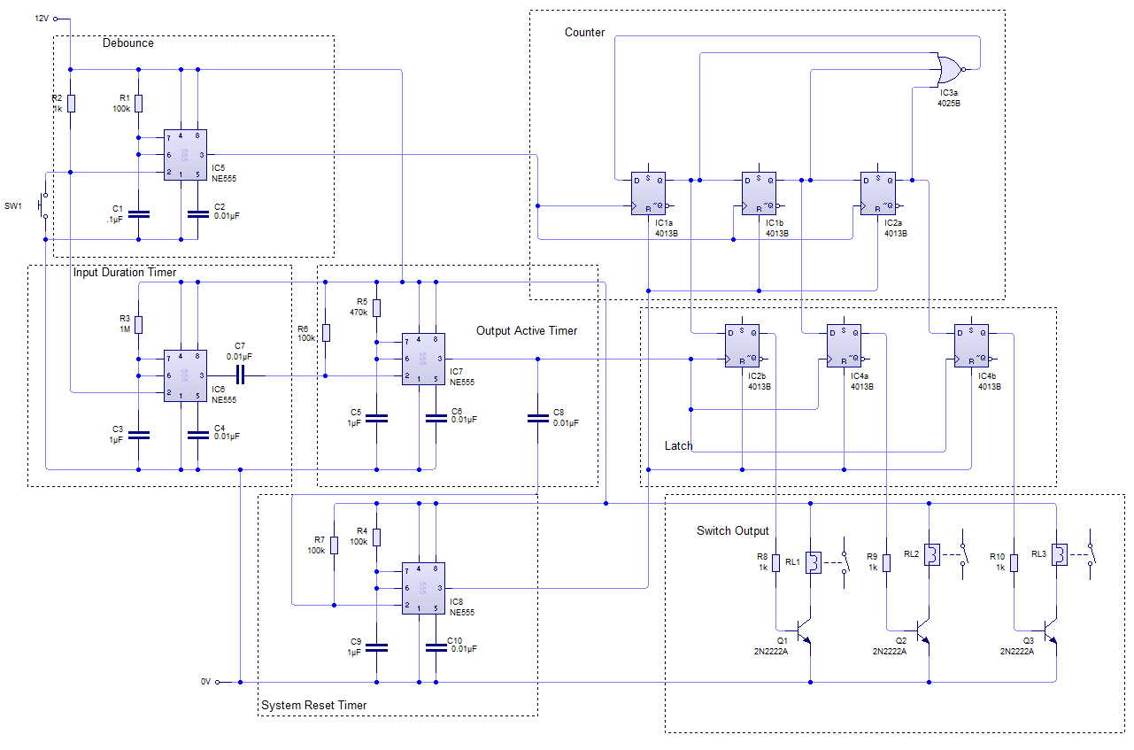
The counter is built from standard D-Type flip-flops, it just shifts a single bit along each time the switch is pressed. The Nor gate is used to ensure only a single bit is shifted and the bit is available at the start.
Rather than using relays and transistors it could be possible to use an electronic switch IC.
Also it may not be possible to connect the switch on the bike to the debounce circuit as I have drawn it, because the switch might be configured as a pull-up rather than pull-down. So a simple transistor and current limiting resistor could be used to invert the signal.


