Author Topic: Control 2 wire fan speed through a PWM 4 wire controller board  (Read 553 times)

0 Members and 1 Guest are viewing this topic.

Offline YouCanDoItTopic starter

  • Regular Contributor
  • *
  • Posts: 85
  • Country: it
Hello to all,
I'm opening this topic because I want to buy this PWM Fan Temperature Control Governor (link):


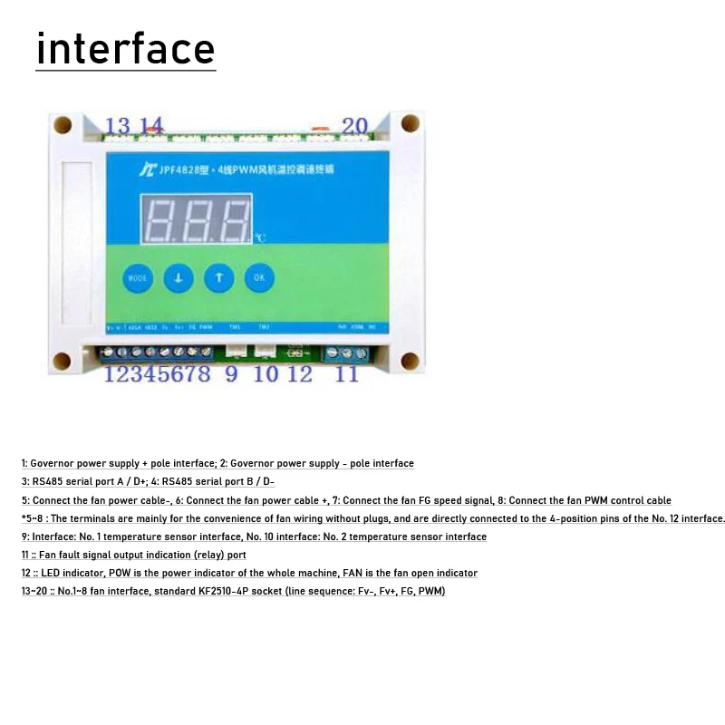
Basically the governor automatically regulate a connected fan speed based on the detected ambient temperature.
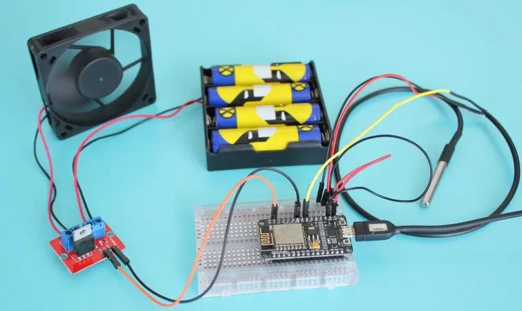
The devices I want to connect:

Main problem is that the above fan is a 2 wire fan, so it will not work as is.
I'm wondering if the controller will be able to control fan speed if I connect the fan through a MOSFET IRF520. From what I saw it seems to be possible, but samples show arduino and I'm not sure if can work at all with the board I want to buy:


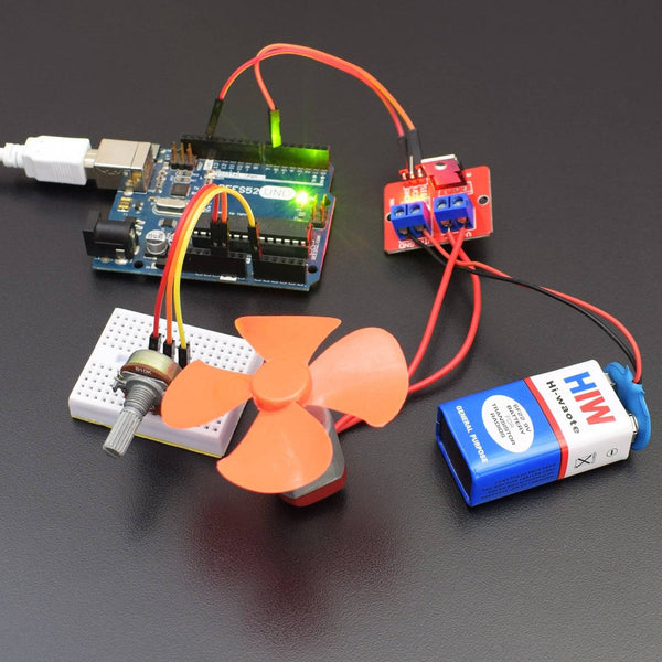
There are other adapters in AE which seems to do similar jobs, but I have no idea on what could be the right one for my specific case. I suppose that IRF520 or similar modules convert PWN signals into DC, so I assume that it should work even with the water pump, right?

This is a new topic opened as consequence of this one. Basically it was the same kind of controller, but designed for 2 wire fans. Main problem was maximum current supported by the fan interface (3A while the fan I need to use, as you can see, is 6A). No one has been able to help, so I'm opening this topic to see if I can achieve the result I want with a different approach, but the problem I have now is the inverse: the controller seems to be able to provide the power required by the fan (maximum drive current is 12A although I'm not sure is enough), but I have no idea if there are ways to make it work with 2 wire fan.

Any help would be very appreciated.
Thanks
 

Online Kurets

  • Contributor
  • Posts: 23
  • Country: se
Re: Control 2 wire fan speed through a PWM 4 wire controller board
« Reply #1 on: July 19, 2024, 07:34:42 pm »
The linked IRF520 module will not do what you want. It is just a very bad breakout board for the FET without gate driving, relying fully on the MCU/whatever to drive the gate. Switching will be very slow and burn the FET.

That said, it is also not a good idea to PWM the supply to a 2-wire brushless fan as it overstresses the input filter.

The better solution here is to use the PWM to feed a gate driver and "inverse buck" converter (low side switch) to generate a sufficiently stable DC voltage. Although designing a 6A output buck converter is not a trivial task in itself.
 
The following users thanked this post: YouCanDoIt

Offline YouCanDoItTopic starter

  • Regular Contributor
  • *
  • Posts: 85
  • Country: it
Re: Control 2 wire fan speed through a PWM 4 wire controller board
« Reply #2 on: July 20, 2024, 03:21:14 am »
Many thanks Kurets! It would have been a very big mistake the IRF520 module and what I want to do seems much harder than I thought!

The better solution here is to use the PWM to feed a gate driver and "inverse buck" converter (low side switch) to generate a sufficiently stable DC voltage. Although designing a 6A output buck converter is not a trivial task in itself.
I think I have understood very little of what you said. Can you link me a ready made adapter suitable for this job and write a few words on how is supposed to be connected?

Many thanks, I really appreciate!
 

Offline Refrigerator

  • Super Contributor
  • ***
  • Posts: 1575
  • Country: lt
Re: Control 2 wire fan speed through a PWM 4 wire controller board
« Reply #3 on: July 23, 2024, 09:04:50 am »
Looks like your fan driver has an output for fan fault, which means that the speed feedback is used to detect if the fan is spinning or not. You may want to check if this is true, so that it doesn't cause problems in the future, because your fan does not have a speed feedback.

The linked IRF520 module will not do what you want. It is just a very bad breakout board for the FET without gate driving, relying fully on the MCU/whatever to drive the gate. Switching will be very slow and burn the FET.

That said, it is also not a good idea to PWM the supply to a 2-wire brushless fan as it overstresses the input filter.

The better solution here is to use the PWM to feed a gate driver and "inverse buck" converter (low side switch) to generate a sufficiently stable DC voltage. Although designing a 6A output buck converter is not a trivial task in itself.

Looking at the assembly diagram shows that this is a simple 775 style brushed motor. Usually these act like an inductor with added noise. PWM-ing them is fine and is the way they're controlled most of the time, although a buck-stage can be used as a point for improvement, which would reduce electrical noise and PWM whine.

Here's a pretty good specification regarding 4-wire fans and their control signals:
https://www.intel.com/content/dam/support/us/en/documents/intel-nuc/intel-4wire-pwm-fans-specs.pdf
I have a blog at http://brimmingideas.blogspot.com/ . Now less empty than ever before !
An expert of making MOSFETs explode.
 
The following users thanked this post: YouCanDoIt

Offline YouCanDoItTopic starter

  • Regular Contributor
  • *
  • Posts: 85
  • Country: it
Re: Control 2 wire fan speed through a PWM 4 wire controller board
« Reply #4 on: July 23, 2024, 09:46:03 pm »
I'm very glad to see someone that knows well how works this stuff.
Looks like your fan driver has an output for fan fault, which means that the speed feedback is used to detect if the fan is spinning or not. You may want to check if this is true, so that it doesn't cause problems in the future, because your fan does not have a speed feedback.
This is very hard to discover. This means that without a speed feedback the controller goes immediately in alarm mode, right? Any way to disable such check? Shouldn't a PWM-DC adaptor be able to provide a speed feedback by converting DC to the equivalent PWM signal?
These are the only informations I have been able to find from the attached google translated manual (the manual may contain additional useful infos):

The linked IRF520 module will not do what you want. It is just a very bad breakout board for the FET without gate driving, relying fully on the MCU/whatever to drive the gate. Switching will be very slow and burn the FET.

That said, it is also not a good idea to PWM the supply to a 2-wire brushless fan as it overstresses the input filter.

The better solution here is to use the PWM to feed a gate driver and "inverse buck" converter (low side switch) to generate a sufficiently stable DC voltage. Although designing a 6A output buck converter is not a trivial task in itself.

Looking at the assembly diagram shows that this is a simple 775 style brushed motor. Usually these act like an inductor with added noise. PWM-ing them is fine and is the way they're controlled most of the time, although a buck-stage can be used as a point for improvement, which would reduce electrical noise and PWM whine.

Here's a pretty good specification regarding 4-wire fans and their control signals:
https://www.intel.com/content/dam/support/us/en/documents/intel-nuc/intel-4wire-pwm-fans-specs.pdf
Do you mean that a PWM controlled fan emit more noise than a non PWM controlled fan running at full speed?
I'm lost here.

Let me try to make it easier...
If I connect the fan as is (just the red and black wire) I can expect the fan running at full speed all of the time or not running at all. If this is correct, than I suppose I can't do any modification on the board and I need an adapter that basically mimics all the PWM features that the controller expect by converting DC signal into PWM signals.
This is the only easy solution I can think of.

There are several adapters in AE, but I have no idea on what are the right ones...

Voltage to PWM Conversion Module 5V-12V Single Chip Embedded Adjustabl Converter Power Board 0-5V/0-10V to 0-100% PWM


1PCS DC 12V 2CH DAC Module 0-5V 0-10V PWM to Voltage Analog Converter RS485 Modbus RTU Board Power Supply For arduino Board


0-5V/0-10V Frequency to Voltage Module PWM to DAC Converter PLC MCU FPGA Analog IO Expansion Board Signal Generator


New DC 1.8V 3 V 5 V 6 V 12V 2 A PWM Motor Speed Controller Low Voltage Motor Speed Controller PWM 0~100% Adjustable Drive Module


This is the project I'm partially using as inspiration:


It uses the same blower fan as mine and, as you can see, the guy is able to control the speed fan through a switch. Such design is very easy to apply, but it's just a speed regulation manually controlled through a potentiometer. It's a completely different story when the regulation has to be done and automated through a controller board. Although I believe this is possible, there are many parameters to consider in order to purchase the right adaptor. I have not been able to find any project showing a similar setup, so mine would be just a leap in the dark.
« Last Edit: July 23, 2024, 09:47:45 pm by YouCanDoIt »
 

Offline YouCanDoItTopic starter

  • Regular Contributor
  • *
  • Posts: 85
  • Country: it
Re: Control 2 wire fan speed through a PWM 4 wire controller board
« Reply #5 on: July 25, 2024, 08:46:22 pm »
I'm afraid that no one here know how to make it work with a concrete sample of the needed parts (adapters etc).

Instead to leave this thread dead due to the lack of a solution, people that need to do the same can check for the solution I posted in my other thread.

it works with 2 wire fans, but keep in mind that there are lot of limitations. However, still better than nothing!


Share me

Digg  Facebook  SlashDot  Delicious  Technorati  Twitter  Google  Yahoo
Smf