As promised, especially thanks to Hero999's idea, here are the results so far.
Method and test details :
- The setup was using adj. bench power supply and Fluke 287 that has 10 Mega Ohm input resistance as in the specification.
- Using this arrangement, so at every beginning of each test, the CUT was connected directly to the PS with the switch closed, and left for about 5 minutes, and then opened the switch to start the measurement.

The CUTs :

Top left to right :
Sanyo Oscon 150 uF 16V , Nichicon 1000uF 100V (PR series) , Nippon ChemiCon (LXZ Series) 1000uF 16V
Bottom left to right :
Polypropylene 560 nF 400V and polypropylene 330 nF 2000V
PS : Not sure about bottom red plastic caps brand or the type as well, so CMIIW.
Datasheet for the electrolytic caps can be found here (stolen from BadCaps forum) ->
Electrolytic Datasheet Repository (suggesting you to bookmark it if you haven't

)
The results :
Sanyo (OSCON Series) 150 uF 16 V (light blue colored/top left)
Test voltage = 16 V
Measured voltage drop = 3.7 volt (more detail below especially for this cap)
Equivalent leak
= Voltage measured / DMM Internal Resistance
= 3.7 Volt / 10 Mega Ohm
= 0.37 uA leakage
Nichicon (PR Series) 1000 uF 100 V (brown/top middle)
Test voltage = 37 V (NOTE : My adj PSU maxed out at 37 Volt, so this is the highest test voltage)
Measured voltage drop = 7.8V -> 0.78 uA leakage
Nippon ChemiCon (LXZ Series) 1000uF 16 V (dark blue/top right)
Test voltage = 16 V
Measured voltage drop = 0.7V -> 0.07 uA leakage
Polypropylene 560 nF 400 V (bright red/bottom left) PS : Seen as photo below.
Test voltage = 37 V
Measured voltage drop = 0.3 mili Volt -> 0.03 uA leakage
Polypropylene 330 nF 2000 V (dark red/bottom right)
Test voltage = 37 V
Measured voltage drop = 0.4 mili Volt -> 0.04 uA leakage
Here is how the "quick n dirty" test jig looks like when measuring that plastic low leakage cap.


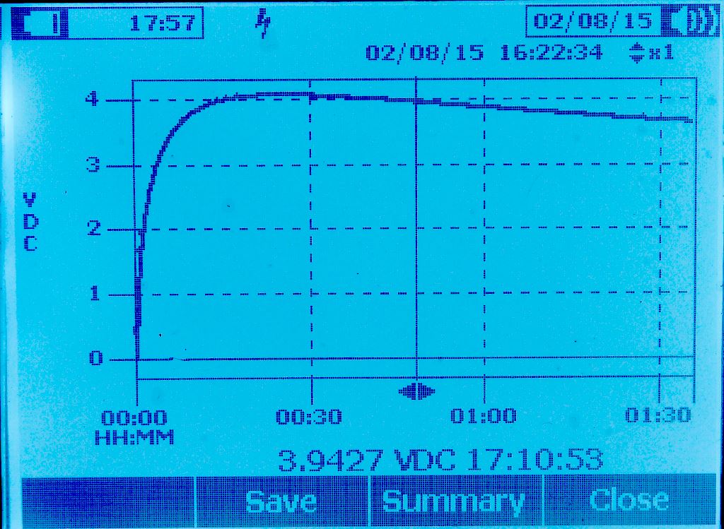
Found an interesting situation when measuring the polymer cap Sanyo OSCON and other two electrolytic caps as well. The leakage seems to have "curve", I just let the chart to tell the detail here.
The logged result (DMM measured voltage) once the switch was opened (after it was closed for 5 minutes for the cap to get charged and "settled").
Log interval is one second for > 1.5 hours.

Do these measurements valid (good enough) as in "quick n dirty" way to measure cap leakage ? Any other comments are welcome.
Again, thanks to Hero999.